Tel:
+86 13143444311
Email:sst@szsst88.com
Fax:+0086-755-27322278
Address:Building 9, First Industrial Zone, Tantou Industrial City, Songgang Street, Baoan District, Shenzhen 518105, Guangdong, China
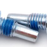
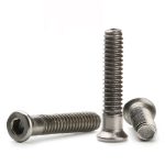
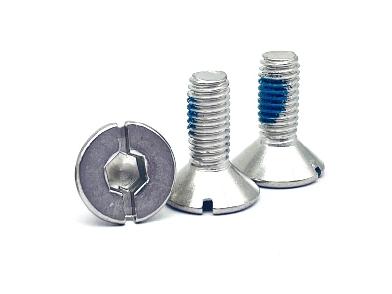
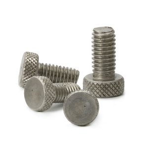
Type:Knurled head locking screw (captive), straight knurl knob, single slot, cone seat, half thread (Non-Standard)
Materials:Carbon Steel (wire for multi-station heading); stainless on request
Surface treatment:Eco Nickel Plated, 3 to 8 um per surface
Head Type:Knurled cylindrical knob 16.00, flat face, straight knurl on the rim
Drive:Single slot across the full face, 1.60 wide; the knurl is the hand drive
Seat:Cone under the head; angle and seat diameter per drawing
Neck:Plain neck 6.00, held below the thread major diameter - the captive zone
Thread:Machine thread M5, rolled 60 degree, 13.00 long to the neck
Point:Blunt end with a small chamfer; no taper, no drill point
Forming:Multi-station heading, knurl formed in the die, slot cut, thread rolled, eco nickel plated, sorted
Size:M1 M2 M3 M4 M5 M6 M7 M8 M9 M10 M14
Number:66
We manufacture knurled head locking screws with a straight-knurled knob, a cone seat, a plain captive neck and a half machine thread, in carbon steel with an eco nickel finish. Knob, cone, neck and thread are taken from your drawing, down to the recorded 16 mm knob and 6 mm neck.
Watch the factory video·Email sst@szsst88.com
ISO 9001:2015 · Manufacturing since 1998 · 8,678+ customers · 89 countries and regions
Made to order – there is no stock catalogue. Each part is produced to your drawing, and production starts after drawing review and first-article approval.
A knurled head locking screw is a captive thumbscrew: a screw with a knurled knob instead of a conventional head, a cone seat under the knob and a plain neck below the thread that stays in the panel so the screw cannot be lost. The recorded item on this page has a 16.00 mm knob, a 1.60 mm slot, a 6.00 mm plain neck and an M5 × 13.00 mm thread, in carbon steel with an eco nickel finish, with Number 66.
Knob instead of head. A 16 mm cylinder with a straight knurl around the rim. The diameter is what gives the fingers their leverage, and the knurl is what stops them slipping on a plated surface.
Cone seat. Under the knob there is a shallow cone rather than a flat bearing face. It centres the screw in a countersunk panel hole and pulls the panel down evenly, which on a hinged cover also compresses the gasket around the hole.
Captive neck. The 6.00 mm plain neck is below the thread major diameter, and it is the zone a retaining ring or a panel escutcheon grips. That is what makes the screw captive: it turns and travels, but it stays with the panel when the cover is opened.
Two drives. The straight knurl is the hand drive; a 1.60 mm slot across the full face is there for a blade when the panel is stiff or the screw has been in place for a while. Both work on the same part and neither interferes with the other.
Together these decide the assembly: the knob turns by hand, the cone centres and seals, the neck keeps the screw on the panel, and the nickel finish keeps the knob bright in a visible location.
The body is carbon steel wire, with grade and heat number on the batch record; stainless is available on request for the same form. The knob is upset on a multi-station header and the straight knurl is formed in the die rather than cut, so the flutes are continuous and the crown edge stays clean.
The slot is cut after the knurl and before plating. Cutting it after knurling keeps the slot concentric with the shank, and cutting it before plating means the slot is plated with the rest of the part, which is what keeps the nickel from accumulating only at the edges.
The cone seat is formed in the heading die under the knob. Its angle and seat diameter have to match the countersink in the panel; a cone that is too steep sits on a narrow ring and marks the panel, and one that is too shallow bottoms in the countersink and leaves a gap at the panel face. Both are checked on the first article against the customer’s panel.
The neck is left plain and turned below the thread major diameter. Its length of 6.00 mm is the captive zone, and it is the dimension a retaining ring or an escutcheon is designed around. Turning it below the major diameter is what allows a clip or a plate to pass over it and then stop at the thread.
The thread is rolled from the neck to the blunt point. On a knurled head locking screw the thread is deliberately short relative to the knob: the screw has to travel through the captive zone before it engages, and the engaged length is what the drawing quotes. On a knurled head locking screw that travel is quoted as a range, not only as a thread length.
The family is quoted from M1 to M14, with M1, M2, M3, M4, M5, M6, M7, M8, M9, M10 and M14 in the recorded range. Custom lengths up to 2,000 mm are subject to DFM review after drawing submission. The recorded configuration on this page is a specific M5 part, and its numbers show how the dimensions fit together.
| Item | Recorded value | What it controls |
|---|---|---|
| Knob diameter | 16.00 mm | Leverage for fingers; clearance around the knob |
| Knob face | Flat, straight knurl on the rim | Grip and appearance |
| Slot | 1.60 mm wide, across the full face | Blade drive when the knob is not enough |
| Cone seat | Angle and seat diameter per drawing | Centring and gasket compression |
| Plain neck | 6.00 mm, below thread major diameter | The captive zone |
| Thread | M5, 13.00 mm long to the neck | Engagement in the tapped hole |
| Plating | Eco nickel, 3 to 8 µm per surface | Brightness; thread gauged after plating |
The numbers are worth reading together because they explain the part. A 16 mm knob on an M5 thread is a hand-drive ratio of about three to one: enough leverage to compress a gasket, not enough to strip a thread by hand. A 6 mm neck and a 13 mm thread mean the screw travels 19 mm in total, so the panel it is captive in has to allow that travel.
Slot width follows the knob, not the thread. A 1.60 mm slot is a standard blade width, and it is cut across the full face so the blade can be used at any orientation without hunting for a groove. On a plated part the slot is checked after plating, because the same 3 to 8 µm that keeps the knob bright also narrows the slot. Every batch of knurled head locking screws is checked on both, in the plated condition.
A knurled head locking screw is specified where a cover or a panel is opened in service and the fastener must not be lost. The features that make that work also set the limits of the part.
| Feature | What it gives | What it costs |
|---|---|---|
| Captive neck | Screw stays with the panel; nothing to drop | The panel needs a retainer or an escutcheon |
| Cone seat | Centring and even gasket load | Countersink angle must match the cone |
| Knurled knob | Hand tightening without tools | Torque limited to what fingers can apply |
| Slot in the face | A blade can finish or free the screw | A deep slot thins the knob centre |
| Nickel plating | Bright, hard, visible finish | Adds a few microns; slot and thread re-checked |
Captivity is the point of the part and the part most often left out of a specification. The neck alone does not make a screw captive; it gives the retainer somewhere to sit. Where the panel has no retainer, the screw is simply a thumbscrew with a step, and the drawing should say so rather than implying a function the assembly cannot deliver. That distinction is what separates a captive knurled head locking screw from a plain thumbscrew.
The cone is what makes the part seal as well as centre. On an access cover the panel sits in a countersink, and the cone pulls it down evenly so the gasket around the hole is compressed in a ring rather than at one point. That is why the cone angle is a quoted dimension and not a die detail: an 82-degree cone in a 90-degree countersink touches on a line and leaks.
The two drives cover two different situations. The knurl is what the operator uses every day, with the screw finger-tight; the slot is what a technician uses when the cover has been closed for a long time or the gasket has taken a set and the screw needs a little more than fingers can give. Both are part of the knurled head locking screw design rather than an afterthought.
The recorded finish is eco nickel at 3 to 8 µm per surface. Nickel gives a bright, hard surface that holds up on a knob that is handled daily, and it is the usual finish for a visible captive screw on an enclosure.
| Finish | How it protects | Effect on slot, thread and knob | Typical use |
|---|---|---|---|
| Eco nickel 3 to 8 µm | Hard metallic deposit, bright | Slot narrows; thread gauged after | Visible enclosure hardware |
| White zinc | Sacrificial zinc, blue-white passivation | Thin; thread gauged after | General indoor panels |
| Black oxide | Thin conversion coat, oiled | Almost no change | Black instrument hardware |
| Zinc nickel | Alloy layer, higher corrosion resistance | Thicker; thread and slot re-checked | Wet or industrial service |
| Stainless (same form) | Alloy provides protection | No coating | Wash-down and coastal use |
Plating thickness matters on this part in two places: the thread and the slot. The thread is rolled before plating and gauged after, because 3 to 8 µm on each flank is enough to change a GO gauge from passing to tight. The slot narrows by the same amount on both walls, so a 1.60 mm slot is checked with the blade and not only with a gauge.
Nickel on a knurled knob also changes how it feels. A heavy deposit rounds the flute crests and makes the knob slippery in a gloved hand, which on a hand-drive part is a real loss of function. That is why the range is 3 to 8 µm rather than a single figure: the low end keeps the knurl sharp, the high end gives the brightness.
Three assemblies where a captive knob is the point of the design:
| Where it sits | The screw holds a door or a hinged cover whose panel has a countersunk hole and a retainer, so the screw stays with the cover when it is opened. |
| When it goes wrong | A loose screw left on the floor of a switch room is a hazard, and a flat head instead of a cone leaves the gasket unevenly compressed. |
| Why it happens | The cover is opened for maintenance, the panel is earthed, and the screw has to be captive. |
| What we control | Cone angle checked against the panel countersink, neck length against the retainer, slot checked after plating. |
| Where it sits | The screw fixes a blanking plate or an access panel that is opened repeatedly and must not rattle when it is closed. |
| When it goes wrong | A loose thumbscrew is lost within a week, and a knob that is too small cannot be turned by hand when the panel is cold. |
| Why it happens | The panel is thin, the fixing is visible, and the same screw is used many times. |
| What we control | Knob diameter and knurl checked for grip, thread gauged after plating, first article fitted in the panel. |
| Where it sits | The screw closes a guard or an inspection cover on a machine that is serviced on a schedule, with a gasket under the panel. |
| When it goes wrong | A screw that is not captive is dropped inside the machine, and a cone that does not match the countersink leaks or lets the cover rattle. |
| Why it happens | The cover is opened on a schedule, the joint is sealed, and the machine is in production. |
| What we control | Cone seat and neck checked on the first article, plating thickness recorded per batch. |
Four reasons that matter on a captive screw, each tied to what the drawing has to prove:
|
Neck and retainer reviewed together
The neck length and diameter, the cone angle and the thread length are reviewed against the panel and its retainer, so a screw that cannot be made captive is raised before tooling. Basis: Neck and retainer reviewed as one set. |
Knurl, slot and thread in one route
The knob and the straight knurl are formed in the die, the slot is cut after knurling, and the thread is rolled before plating. Basis: One route from wire to plated screw. |
|
Slot and thread checked after plating
The slot is checked with the production blade, the thread is gauged in its plated condition, and the cone is fitted in a panel sample. Basis: First article fitted in the panel. |
First article to repeat production
The first article fixes the drawing revision, wire heat, die set, slot width and plating thickness; repeat orders are compared against that record. Basis: First article signed off before the batch is released. |
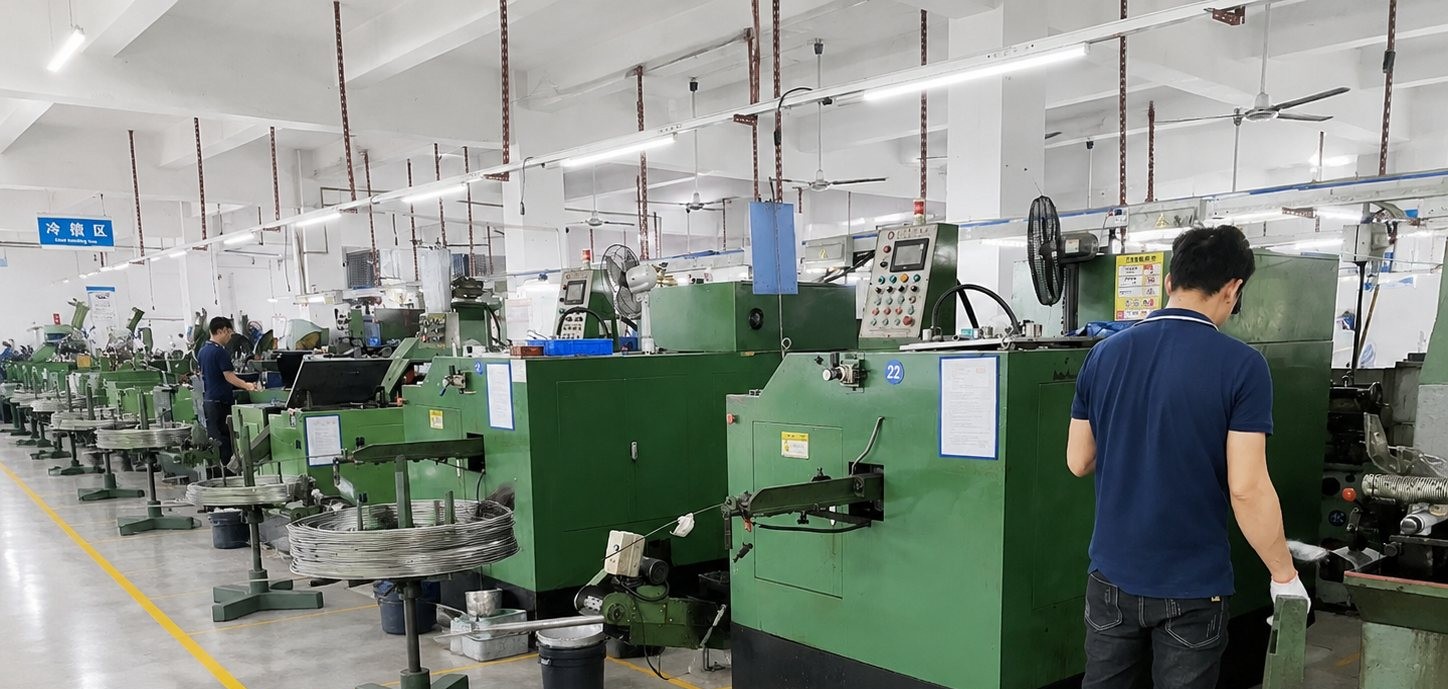
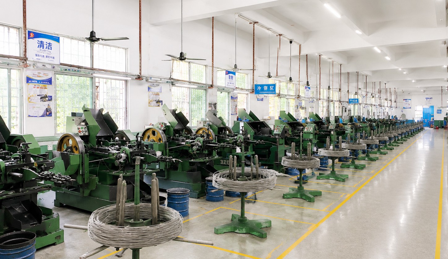
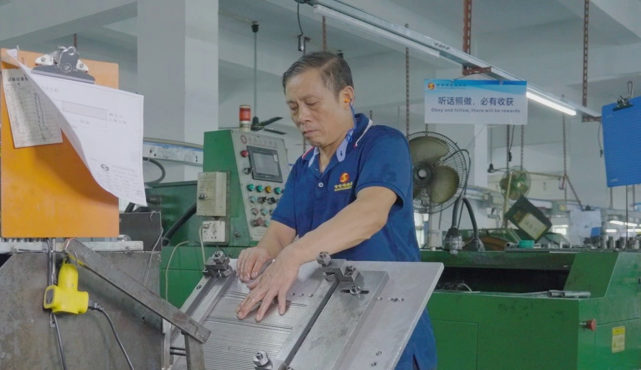
Shi Shi Tong forms these knurled head locking screws on a multi-station header: the knob and the straight knurl are formed in the die, the cone seat is shaped under the knob, the slot is cut across the face, and the machine thread is rolled above the plain neck. The parts are eco nickel plated and sorted. The first part of every run is measured on the knob, the neck and the thread, and fitted in a panel sample, before the batch continues.
|
|
The sequence is what keeps the part true. The knurl is formed first because it moves material, the slot is cut afterwards because it has to be concentric with the shank, and the thread is rolled before plating because plating is part of the final dimension. Changing that order produces a knob that is off centre or a thread that will not gauge after the nickel goes on.
What decides whether a knurled head locking screw passes is the knob, the cone, the neck, the slot, the thread and the plating. The inspection agreement covers those, and the criteria come from the drawing.
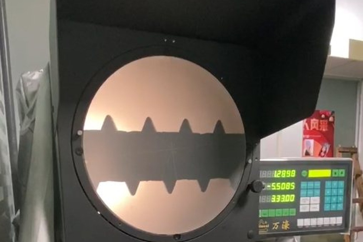
Knob and cone on the projector |
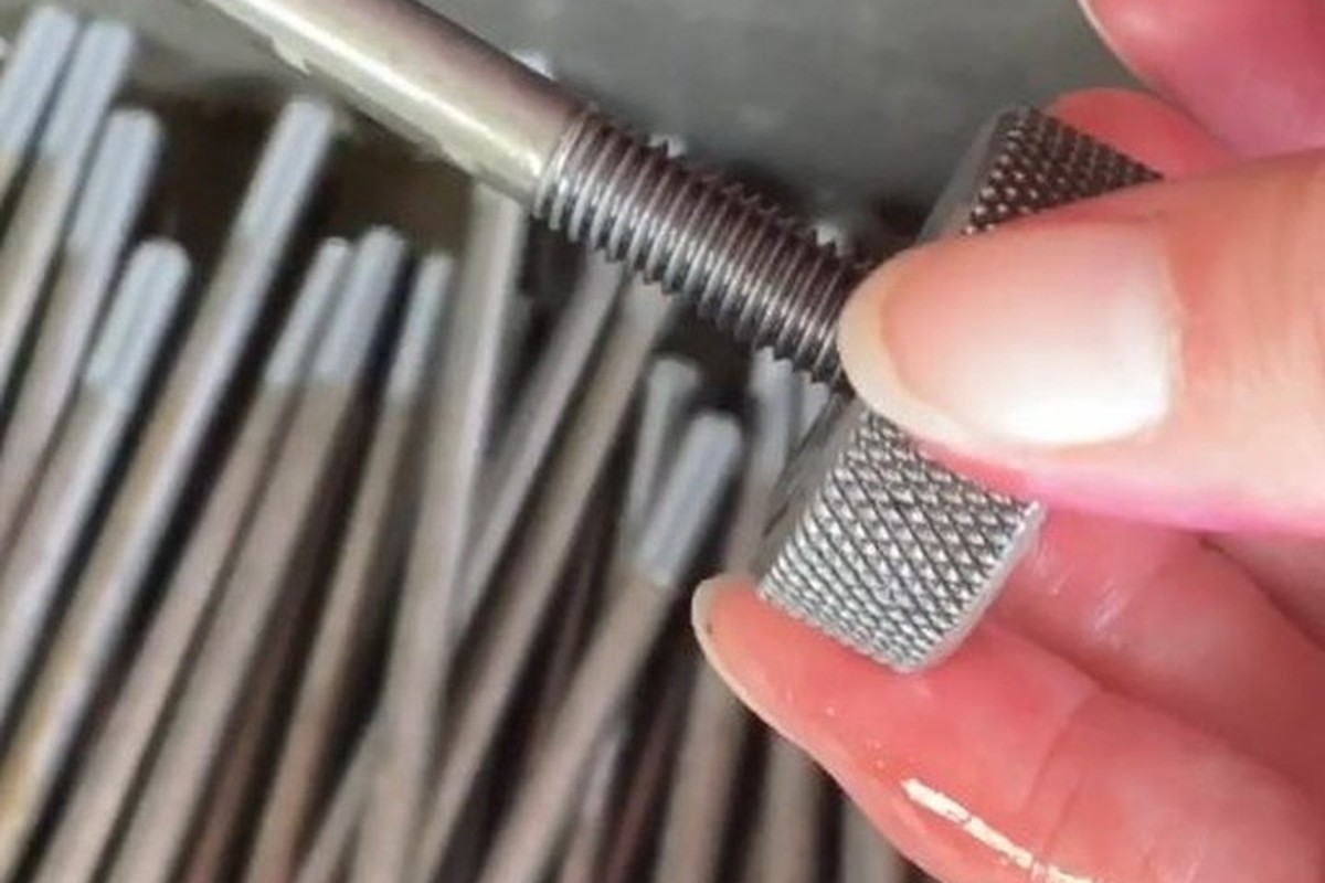
Thread gauged after plating |
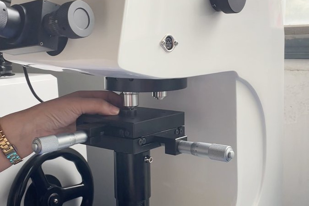
Hardness testing against the property class |
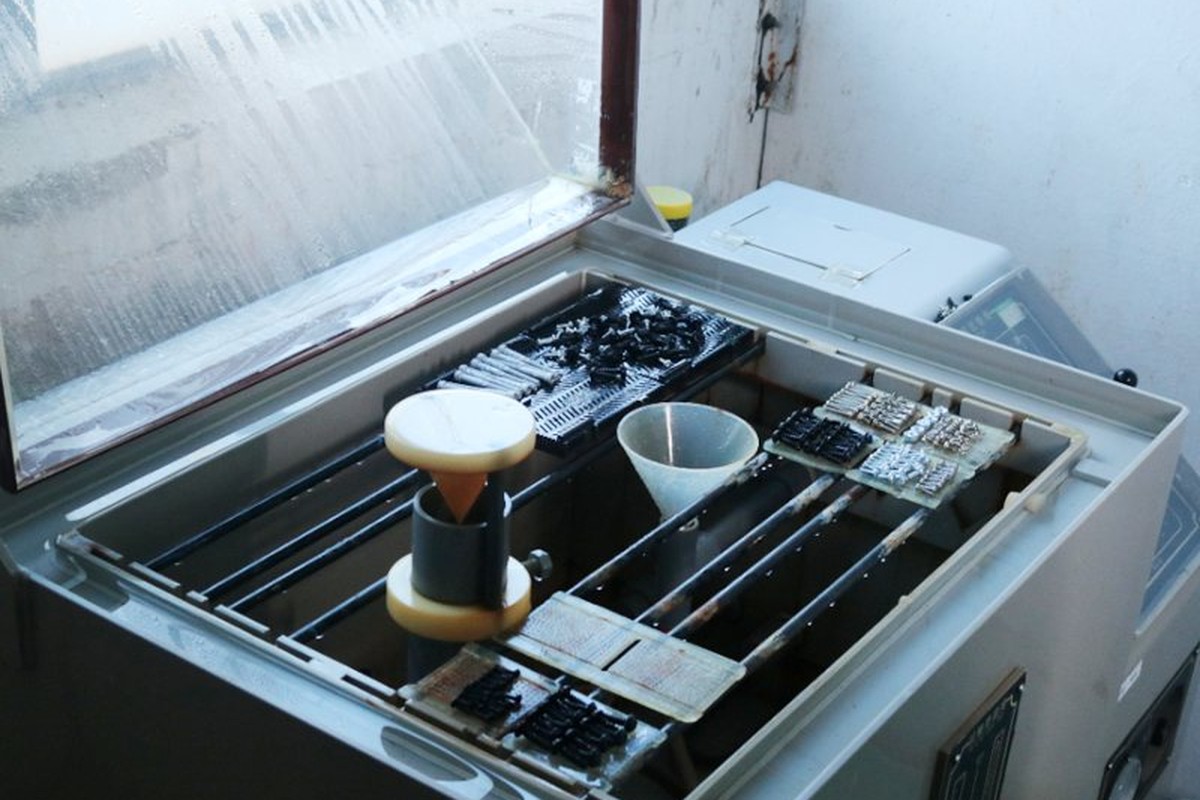
Salt-spray testing of the nickel plate |
The cone is checked by fitting the part in a panel sample with its countersink. Measuring the angle on the projector proves the cone is the angle on the drawing; only the fit proves it seats on a face rather than on a line, and on a gasketed cover that difference is the leak.
The neck is measured for diameter and length, and it is also checked that no thread has crept into it. A rolled thread that runs into the captive zone stops the retainer from passing over, and the screw cannot be fitted at all, which is a failure that shows only at assembly.
Every shipment of knurled head locking screws is traceable to the wire it was made from. The grade and heat number are recorded on the material certificate supplied with the parts, together with the plating thickness record, and the inspection records follow the criteria agreed on the drawing.
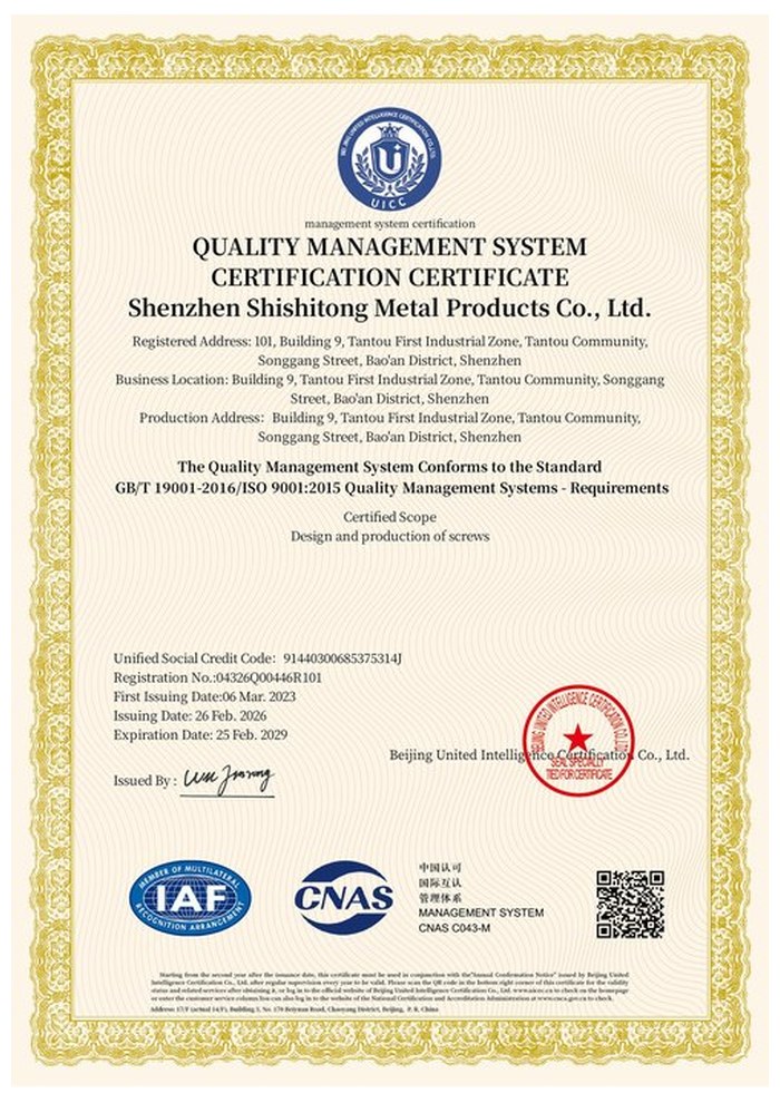
ISO 9001:2015 |
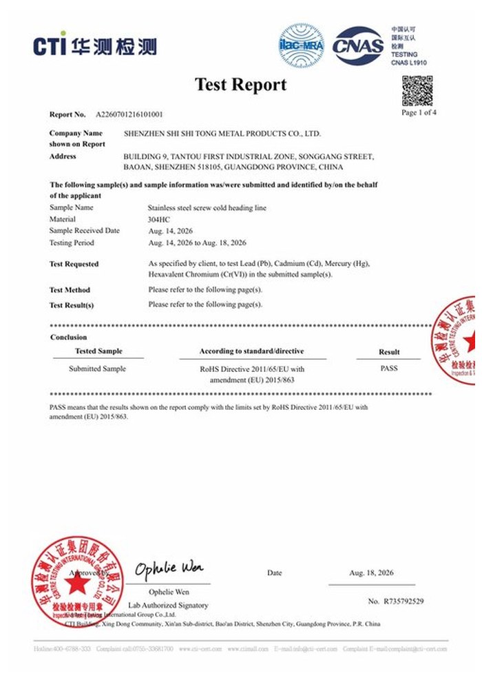
RoHS test report |
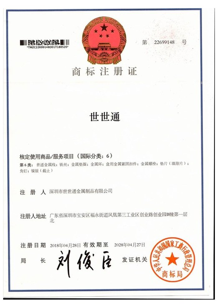
Registered trademark |
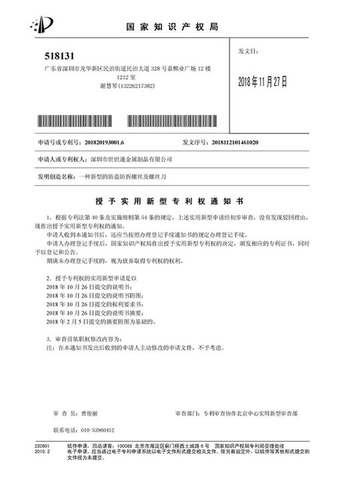
Patent: security screw and driver |
With each batch we supply the material certificate, the inspection record for the criteria on the drawing and, where it is listed, the third-party report for the material or the plating. The documents carry the drawing revision and the batch number, so the paperwork can be matched to the parts.
More than 8,678 customers in 89 countries and regions have ordered from Shi Shi Tong; 87% of orders come from repeat customers and 56% through referrals. Most projects follow the same route: drawing review, first-article approval, then batches checked against that sample. On a captive screw the first article is fitted in the panel with its retainer, because the neck and the cone only prove themselves in the assembly. Buyers visit during the process to review samples and to see how the knurls are formed.
|
8,678+
customers served
|
87%
of orders from repeat customers
|
56%
of orders through referrals
|
89
countries and regions shipped to
|
Buyers and quality engineers visit for sample review, process discussion and supplier audits; the visit is arranged around production so the header and the plating line can be seen on the day the parts run.

Customer group visit – sample review |

Customer group visit – process discussion |

Customer group visit – factory tour |

Customer visit – project kick-off |

Danish customer – drawing review |
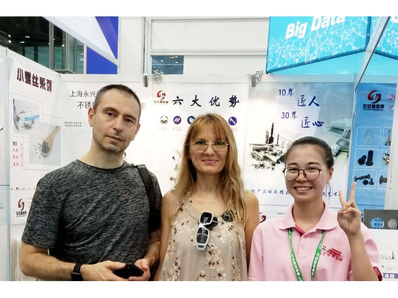
Industry exhibition – meeting customers |
The plain neck below the thread. A retaining ring or the panel itself grips the neck, so the screw turns and travels but stays with the panel when the cover is opened.
It centres the screw in a countersunk hole and pulls the panel down evenly, which compresses a gasket in a ring instead of at one point.
A 16.00 mm knurled knob with a 1.60 mm slot, a 6.00 mm neck and an M5 thread 13.00 mm long, in carbon steel with eco nickel at 3 to 8 µm.
Yes. The thread is gauged after plating, and the slot is checked with the blade, because 3 to 8 µm narrows both. The ranges are agreed on the drawing.
The knurl is the everyday hand drive; the slot lets a blade finish the joint or free a screw that has been closed for a long time.
Knob diameter and face, slot width, cone angle and seat diameter, neck diameter and length, thread size and length, overall travel, plating thickness and material.
How a knurled head locking screw project runs from drawing to repeat delivery:
|
1
Send the drawing or panel sample
|
→ |
2
Cone and neck review
|
→ |
3
First article fitted with the retainer
|
→ |
4
Batch production and repeat orders
|
Each step is confirmed with you before the next one starts; the drawing revision from the first article is what repeat orders are checked against.
For a quotation, send the drawing with the knob diameter and face, slot width, cone angle and seat diameter, neck diameter and length, thread size and length, overall travel, plating thickness and material.
|
Knob diameter
|
Slot width
|
Cone angle and seat
|
|
Neck diameter and length
|
Thread size and length
|
Plating thickness
|
Sending a drawing? The form below does not take attachments. Email the PDF, DXF or STEP file to sst@szsst88.com with the part name and quantity in the subject line – the drawing is reviewed and a quotation follows.

 +86 13143444311
 sst@szsst88.com