Tel:
+86 13143444311
Email:sst@szsst88.com
Fax:+0086-755-27322278
Address:Building 9, First Industrial Zone, Tantou Industrial City, Songgang Street, Baoan District, Shenzhen 518105, Guangdong, China
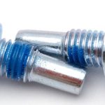
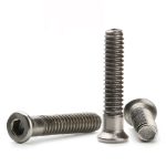
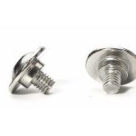
Type:Cap Head Machine Screw, Non-Standard
Materials:Carbon Steel
Surface treatment:Nickel Plated
Head Type:Cap Head (plain cylindrical, no drive recess)
Drive type:No drive recess — plain head face
Thread:Machine thread, rolled, full to the head seat
Process:Multi-station heading, thread rolling, nickel plating
Size:M1 M2 M3 M4 M5 M6 M7 M8 M9 M10 M14
Number:76
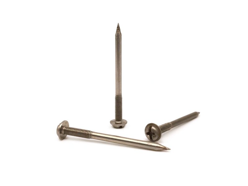
We manufacture cap head machine screws as non-standard parts: a plain cylindrical head with no drive recess in the recorded configuration, a machine thread rolled full to the seat and a nickel finish, quoted from M1 to M14. Head dimensions, head face, thread seat and finish are taken from your drawing.
Watch the factory video·Email sst@szsst88.com
ISO 9001:2015 · Manufacturing since 1998 · 8,678+ customers · 89 countries and regions
Made to order – there is no stock catalogue. Each part is produced to your drawing, and production starts after drawing review and first-article approval.
A cap head machine screw is a machine screw with a plain cylindrical head — the head form that a socket cap screw uses — but supplied here as a non-standard part with no drive recess in the head face. The recorded item on this page is a carbon steel screw with a nickel finish and a machine thread, quoted from M1 to M14 with Number 76.
Cylindrical head. A straight-sided head with a flat top and a flat bearing face underneath. It sits in a counterbore and presents a clean circle on the assembly, which is why the form is used wherever a neat round fixing is wanted.
No drive recess. The recorded configuration has a plain head face: there is no hexagon, no cross and no slot. That is not an omission but a definition of the part — how it is turned is decided by the drawing, not by a standard recess.
Machine thread. The thread engages a tapped hole, a nut or an insert, and it is rolled full to the head seat so the joint clamps as close to the head as the design allows.
Non-standard. The part is made to drawing rather than to a catalogue standard, which is what allows the head to be specified without a recess, or with a drive that the drawing defines separately.
Together these decide the part: the cylindrical head fits the counterbore, the plain face is what the assembly needs, the thread holds the joint, and the nickel finish keeps it bright. That is why a cap head machine screw of this type is specified by head, drive and thread together rather than by thread size alone.
The body of this cap head machine screw is carbon steel wire, with the grade and heat number kept with the batch record. The property class is on the drawing, because it sets the torque the head can take and whether the nickel plated part needs a bake after coating.
The head is formed in a multi-station heading machine: the cylinder is upset, the top face is flattened and the bearing face underneath is formed square to the shank. On a plain head that squareness is the only thing holding the part straight in its counterbore, because there is no recess to guide a driver.
The thread is rolled full to the head seat. That detail matters here: a cap head is usually specified where the joint has to clamp tight against a shoulder, and a plain shank under the head would leave the head standing off the face it is meant to sit on.
The head face is left plain, as the drawing specifies. Where a customer needs a drive, it is added as a separate feature — a socket, a slot or a hex — and the drawing then describes that feature; the standard part and the driven part are different items and are not interchangeable.
The nickel plating is applied after the thread is rolled. It gives a hard, bright surface on the cylindrical wall and the flat face, which is where a visible cap head is judged, and it adds only a few microns to the thread flanks.
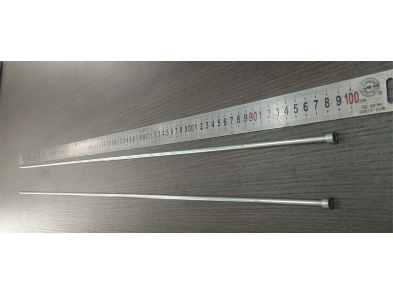
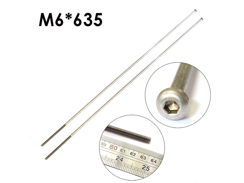
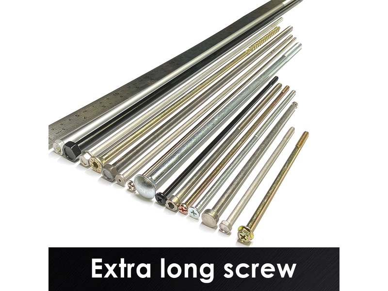
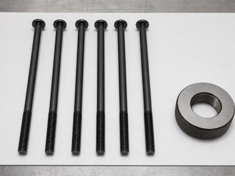
Cap head machine screws of this non-standard type are quoted from M1 to M14 for the thread, with the head diameter and height set per drawing; the recorded configuration is a plated steel part with a plain cylindrical head and a full machine thread. Custom lengths up to 2,000 mm are subject to DFM review after drawing submission.
| Item | How it is defined | What we control |
|---|---|---|
| Head diameter | The cylindrical wall that fits the counterbore | Checked on the projector on the first article |
| Head height | The height above the counterbore | Measured from the bearing face |
| Head face | Plain, or with the drive the drawing specifies | Checked against the drawing |
| Thread size and pitch | The fit in the tapped hole | Gauged after plating |
| Thread to head seat | Whether the thread runs full to the head | Checked on the first article |
| Length | From under the head to the tip | Datum stated on the drawing; measured on the shop plate |
Each size is quoted against the counterbore it sits in. The head diameter, the bore and the head height are reviewed together, because a cap head that is a few hundredths large will not enter the bore and one that is short leaves the wall below the surface.
Length is measured from under the head, and the thread seat is stated separately where the drawing calls for thread right up to the head. On a cap head that is the difference between clamping on a shoulder and standing off it.
A cap head machine screw with a plain face is a part whose function is complete without a drive: it is fitted, seated and left. That is the case on cover plugs, decorative caps, locating studs and parts that are turned by the mating assembly rather than by a tool on the head.
| Situation | What the plain head does | What to specify on the drawing | What we control |
|---|---|---|---|
| Cover plug | Closes a bore and presents a clean circle | Head diameter, height and face finish | Head diameter and face checked on the first article |
| Locating stud | Centres a component in a bore | Head as a shoulder, thread length to the seat | Thread seat and head squareness |
| Driven part | Needs a drive after all | Recess type and size, or a hex on the head | Drive checked with the matching tool |
| Decorative cap | Visible face with no tool marks | Face finish and head edge condition | Face and edge checked against the sample |
The practical consequence is that this part cannot be tightened by hand without a tool that grips the cylindrical wall. Where the assembly needs a drive, the drawing has to add one — a hex socket, a Torx recess or flats on the head — and that changes the part, the tooling and the price.
The cylindrical head itself is still doing useful work. It centres the screw in a counterbore, it spreads the clamp load over a flat bearing face, and it leaves a low, round profile that does not catch on anything. Those are the reasons the form exists; the drive is a separate decision.
Nickel on a plain face shows handling. Because there is no recess to draw the eye, a scuff on the flat face or a mark on the cylindrical wall is the first thing seen, which is why the first article is checked for appearance as well as dimension.
This cap head machine screw is supplied nickel plated. The deposit is hard, bright and thin, and on a plain head that matters more than usual: the whole visible feature is the cylindrical wall and the flat face, with no recess to break up the surface.
| Finish | How it protects | Effect on head and thread | Typical use |
|---|---|---|---|
| Nickel plated | Hard barrier layer, bright | A few microns; thread gauged after | Visible cap heads and cover plugs |
| Zinc plated | Sacrificial zinc layer | A few microns; gauged after | Indoor assemblies, low cost |
| Zinc nickel | Alloy layer, higher corrosion resistance | Thicker; thread re-checked | Wet or mildly corrosive service |
| Black oxide | Conversion layer plus oil | No build-up | Dark visible parts |
| Stainless (equivalent part) | Alloy provides protection | No coating; as formed | Wash-down and outdoor work |
Nickel protects the surface it covers, but it does not protect a scratch the way zinc does. On a part where the head face is the visible feature, that means the packing has to do the protecting: the heads are separated so they cannot rub, and the first piece in a bag is checked for marks.
Packing is part of the specification here. The parts are bagged in counted quantities, labelled with the batch, the material heat and the head dimensions, and packed so the cylindrical walls and flat faces cannot knock against each other in transit.
Three assemblies where a plain cylindrical head is the point of the part:
| Where it sits | The head closes a bore or covers a fixing point and has to read as a clean circle on the finished surface. |
| When it goes wrong | A head that stands proud or sits below the face shows as a step, and a scratched nickel face cannot be touched up. |
| Why it happens | The face is visible, the part is fitted once, and the appearance is inspected. |
| What we control | Head diameter, height and face checked against the sample, and packing verified so the faces do not rub. |
| Where it sits | The head acts as a shoulder that centres a bracket or a plate in a bore, with the thread clamping from the other side. |
| When it goes wrong | A head that is off square tilts the bracket, and a thread that stops short of the seat leaves it loose. |
| Why it happens | The bore is machined, the part is fitted once, and the bracket position matters. |
| What we control | Head squareness and thread seat checked on the first article. |
| Where it sits | The part replaces a standard cap screw where the counterbore and the head height are fixed by existing hardware. |
| When it goes wrong | A part made to thread size but not to the head will not enter the counterbore, and re-machining it in place is not possible. |
| Why it happens | The drawing is fixed by the existing assembly, and the part has to match it exactly. |
| What we control | Head diameter and height measured against the drawing, and the thread gauged per batch. |
Four reasons that matter on a non-standard cylindrical head, each tied to what the drawing has to prove:
|
Head form and drive reviewed first
The head diameter, height and whether the drawing calls for a drive are reviewed before tooling, so a part that cannot be fitted or cannot be turned is raised first. Basis: Head form and drive reviewed before tooling. |
Headed and rolled in one route
The cylindrical head is formed on a multi-station machine and the thread is rolled full to the seat, so the head stays square to the shank. Basis: One route from wire to finished screw. |
|
Head and thread seat checked on the part
The head diameter, height and squareness are measured and the thread seat is checked, on the first article. Basis: First article checked on head and seat. |
First article to repeat production
The first article fixes the drawing revision, wire heat, die set and plating batch; repeat orders are compared against that record. Basis: First article signed off before the batch is released. |
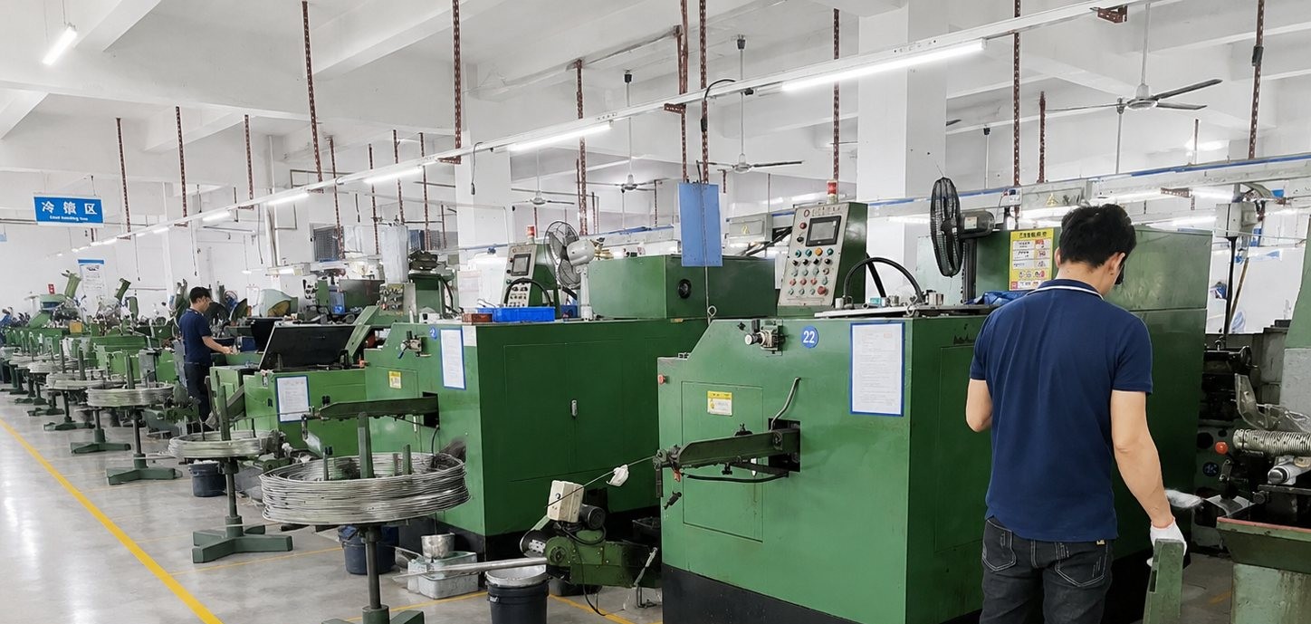
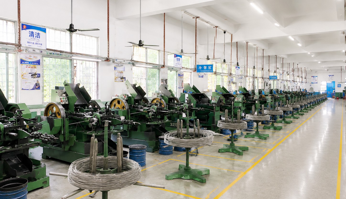
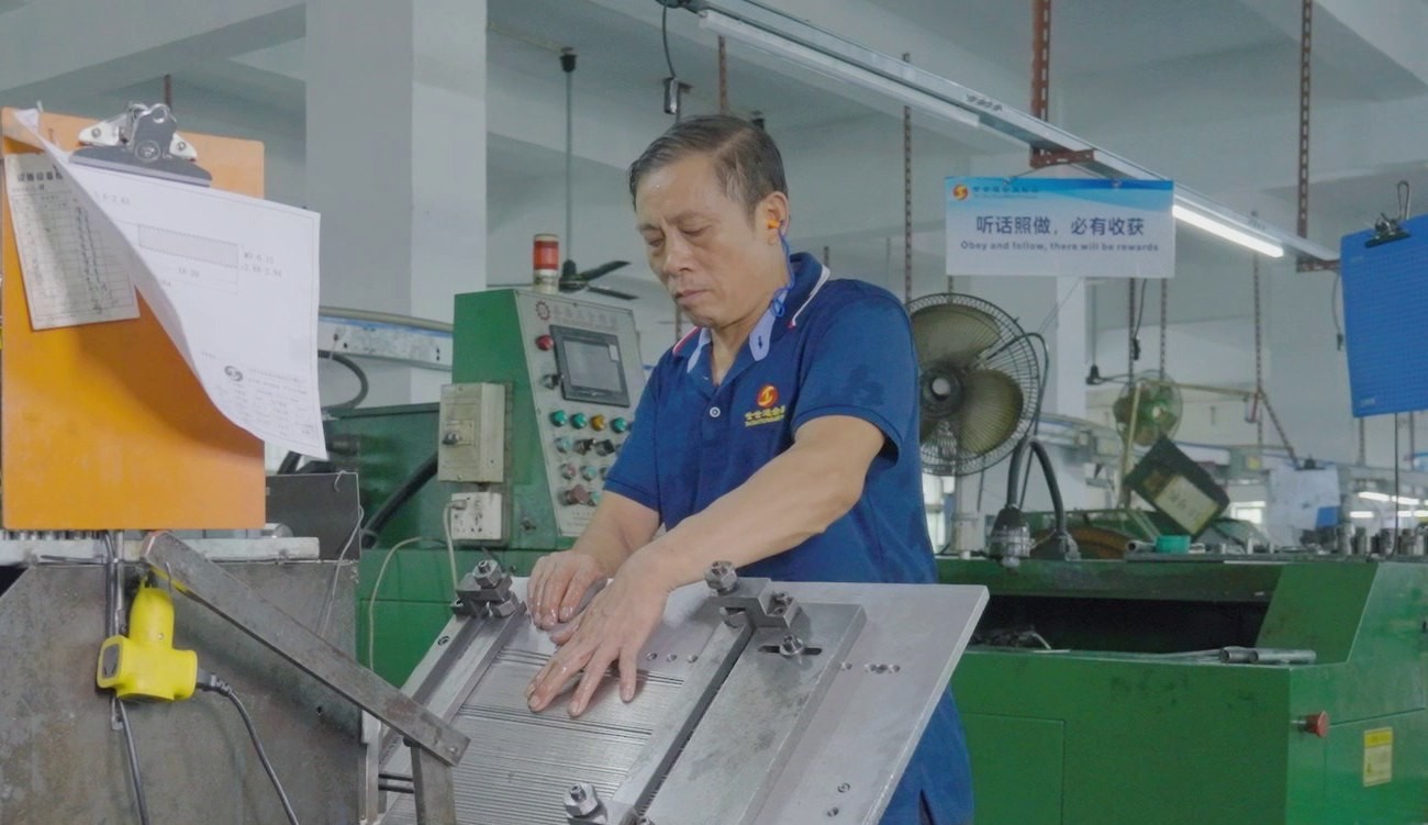
Shi Shi Tong forms these cap head machine screws on a multi-station heading machine that upsets the cylindrical head and flattens the top face, then rolls the machine thread full to the head seat and applies the nickel plating. The first part of every run is measured on the head, checked square to the shank and gauged after plating, before the batch continues.
|
|
Between runs the die insert is changed to the drawing head diameter and height, and the thread rolls to the size; the first part goes to the projector and to the gauges. Where the drawing specifies a drive in the head face, that feature is checked in the same pass, because it is formed with the head and cannot be added later without a second operation.
What decides whether a cap head machine screw passes is the head diameter and height, the squareness of the head to the shank, the condition of the head face and the thread class after plating. The inspection agreement covers those, and the criteria come from the drawing.
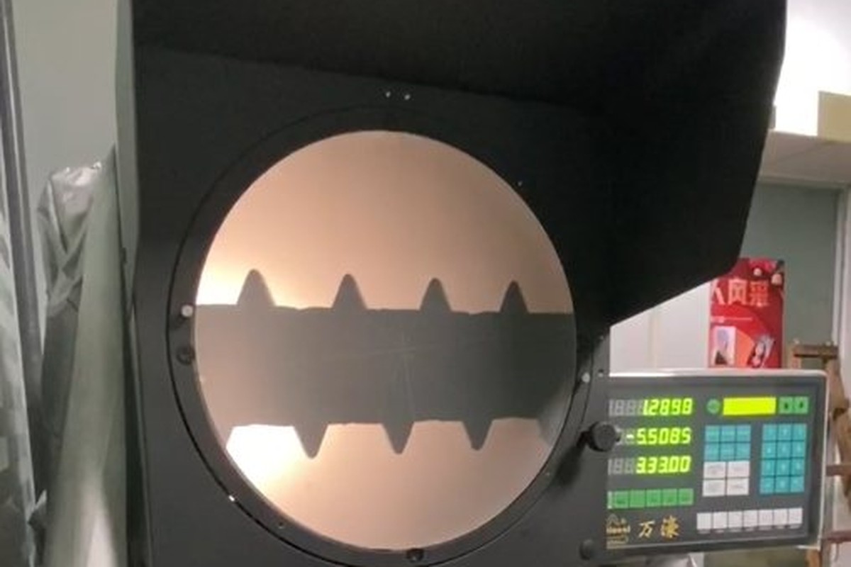
Head diameter and height on the projector |
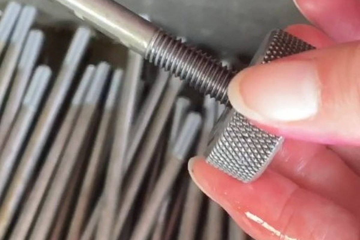
Thread gauged after plating |
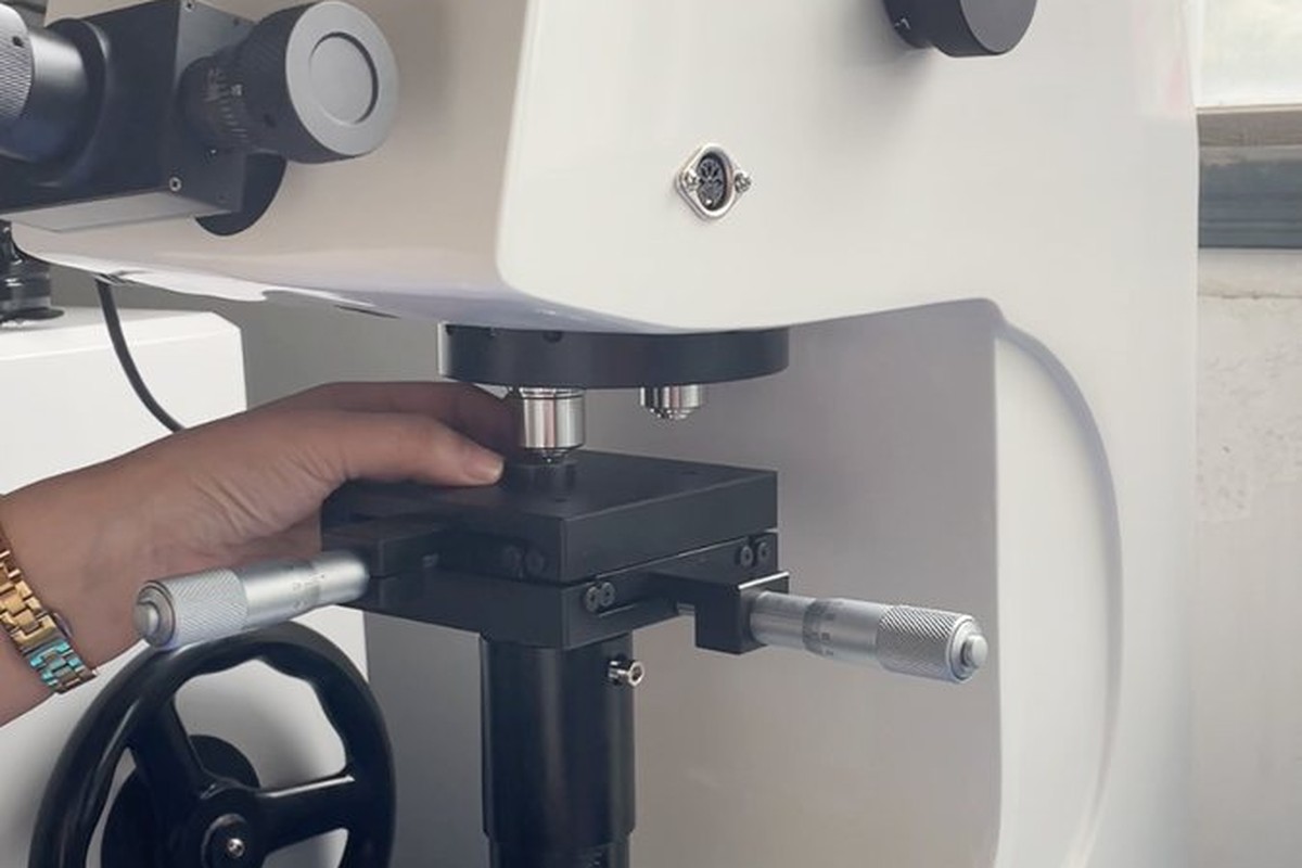
Hardness testing against the property class |
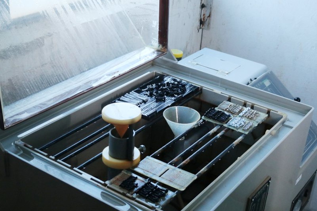
Salt-spray testing of the plated part |
Each batch is recorded against the drawing revision: head and face from the first article, the thread gauged after plating, and the coating batch carried on the label. If the head or the thread seat check fails, the parts back to the last good setting are held and re-checked.
If the finish needs an independent report, it is planned with the batch so the paperwork and the parts ship together under one batch number.
Every shipment of cap head machine screws is traceable to the wire it was made from. The grade, heat number and property class are recorded on the material certificate supplied with the parts, and the inspection records follow the criteria agreed on the drawing.
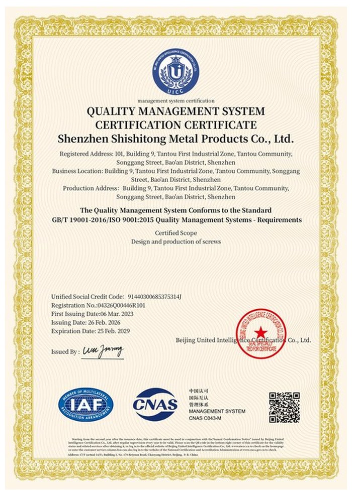
ISO 9001:2015 |
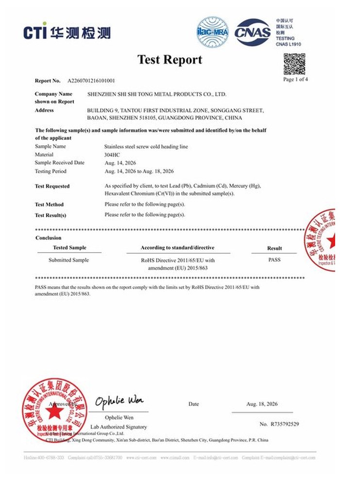
RoHS test report |
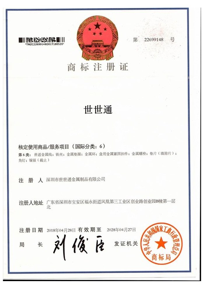
Registered trademark |
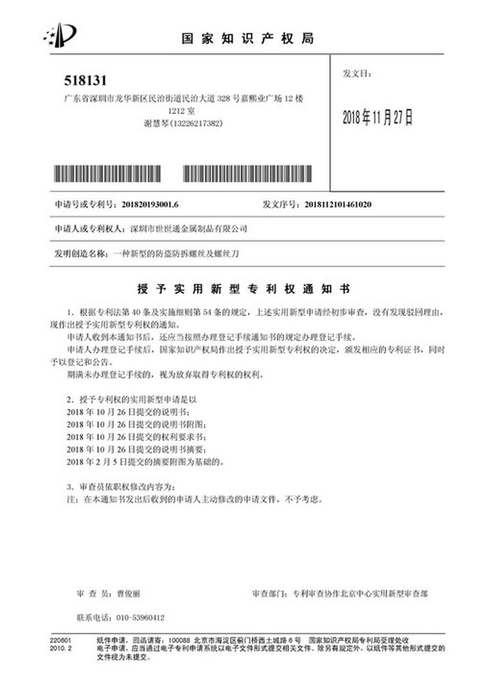
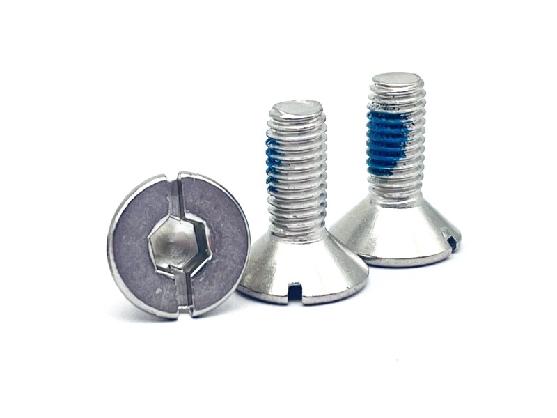
Patent: security screw and driver |
With each batch we supply the material certificate, the inspection record for the criteria on the drawing and, where it is listed, the third-party report for the material or the finish. The documents carry the drawing revision and the batch number, so the paperwork can be matched to the parts.
More than 8,678 customers in 89 countries and regions have ordered from Shi Shi Tong; 87% of orders come from repeat customers and 56% through referrals. Most projects follow the same route: drawing review, first-article approval, then batches checked against that sample. On a non-standard head the first article is fitted into the customer’s counterbore, so the head diameter and height are signed off in the assembly they sit in. Buyers visit during the process to review samples and to see how the heads are formed.
|
8,678+
customers served
|
87%
of orders from repeat customers
|
56%
of orders through referrals
|
89
countries and regions shipped to
|
Buyers and quality engineers visit for sample review, process discussion and supplier audits; the visit is arranged around production so the header and the plating line can be seen on the day the parts run.

Customer group visit – sample review |

Customer group visit – process discussion |

Customer group visit – factory tour |

Customer visit – project kick-off |

Danish customer – drawing review |
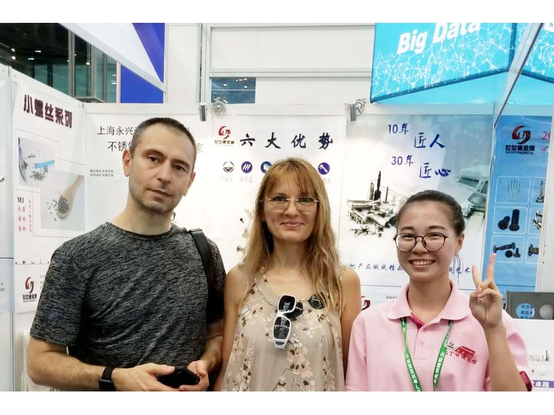
Industry exhibition – meeting customers |
It is a machine screw with a plain cylindrical head, the same head form a socket cap screw uses. This one is a non-standard part with no drive recess, a nickel finish and a machine thread, quoted from M1 to M14.
It is not, unless the drawing adds a drive. As recorded, the head face is plain: the part is used where it is fitted and left, such as a cover plug, a locating stud or a decorative cap.
Yes, but that is a different part. Adding a hex socket, a Torx recess or flats changes the head geometry, the tooling and the price, so the drawing has to specify it from the start.
Because a cap head is usually specified where the joint clamps against a shoulder. A plain shank under the head would leave the head standing off the face it is meant to sit on.
Nickel plating, which gives a hard bright surface on the cylindrical wall and the flat face. For wet or exposed joints a zinc-nickel finish or a stainless part is the better choice.
Head diameter and height, head face condition, drive if any, thread size and pitch, whether the thread runs to the seat, length and datum, material and property class, and finish.
How a cap head machine screw project runs from drawing to repeat delivery:
|
1
Send the drawing or sample
|
→ |
2
Head form and drive review
|
→ |
3
First article in the counterbore
|
→ |
4
Batch production and repeat orders
|
Each step is confirmed with you before the next one starts; the drawing revision from the first article is what repeat orders are checked against.
For a quotation, send the drawing with the head diameter and height, head face condition, any drive needed, thread size and pitch, whether the thread runs to the seat, length and its datum, material and property class, and finish.
|
Head diameter and height
|
Head face and drive
|
Thread size and pitch
|
|
Thread to seat
|
Length and datum
|
Material and finish
|
Sending a drawing? The form below does not take attachments. Email the PDF, DXF or STEP file to sst@szsst88.com with the part name and quantity in the subject line – the drawing is reviewed and a quotation follows.

 +86 13143444311
 sst@szsst88.com