Tel:
+86 13143444311
Email:sst@szsst88.com
Fax:+0086-755-27322278
Address:Building 9, First Industrial Zone, Tantou Industrial City, Songgang Street, Baoan District, Shenzhen 518105, Guangdong, China
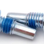
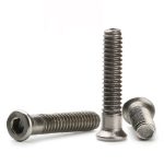
Type:Left Hand Thread Machine Screws
Materials:Aluminum
Surface treatment:Plain
Head Type:Cap Head
Drive:Round Hole
Thread:Left Hand Machine Thread
Point:Blunt
Forming:Turned
Size:M1 M2 M3 M4 M5 M6 M7 M8 M9 M10 M14
Number:25
We turn left hand thread machine screws in aluminium with a cap head and a round-hole drive, quoting them from M1 to M14 in either hand of thread. The hand, pitch, head, bore and length are taken from your drawing and proven with a left-hand gauge on the first article.
Watch the factory video·Email sst@szsst88.com
ISO 9001:2015 · Manufacturing since 1998 · 8,678+ customers · 89 countries and regions
Made to order – there is no stock catalogue. Each part is produced to your drawing, and production starts after drawing review and first-article approval.
Left hand thread machine screws are machine screws whose thread advances when they are turned anticlockwise, so that rotation of the part they hold works the joint tighter instead of backing it out. The recorded item on this page is a turned aluminium screw with a cap head and a plain round-hole drive, quoted from M1 to M14 with Number 25.
Left-hand thread. The helix runs the other way round the shank. Turn it clockwise and it comes out; turn it anticlockwise and it goes in. Everything downstream of that — the gauge, the driver direction, the torque instruction — has to be restated for the hand, which is why it is called out on the drawing rather than assumed.
Cap head. A straight cylinder with a flat bearing face and a chamfered top edge. The bearing face is what seats on the joint, so it is turned square to the axis and left flat enough to bear evenly rather than on one side.
Round-hole drive. A plain bore in the top face instead of a cross, a slot or a hexagon. It is driven with the matching round-hole driver; a Phillips bit or a hex key has nothing to bite and will score the bore instead of turning the screw.
Turned from bar. The head, the bore and the thread are all cut on a lathe rather than headed from wire. A left-hand thread is the reason this route suits the part: the thread can be cut in either hand on the same lathe by reversing the spindle, without a change of die.
Aluminium, plain. Light, non-magnetic and protected by its own oxide film. The alloy is softer than the steel it usually threads into, so the thread is the part that gives first and the clamping load is set with that in mind.
A left-hand thread is cut on a lathe with the spindle run in reverse, or with the lead screw reversed, so that the tool travels away from the shoulder and the carriage follows the helix in the other direction. The thread start therefore sits at the head end and runs out to the blunt end, which is where a left-hand screw wants it: the first turn is guided by the chamfer, and the flank that carries the load is the one facing the head.
The hand of the thread is a property of the tool path, not of the tool. The same insert cuts both hands; what changes is the direction of travel relative to the rotation. That is why a turned part can be quoted in either hand without new tooling, and why a headed part with a rolled thread cannot: a rolled left-hand thread needs a left-hand roll.
The bore is drilled and bored after the head is turned, from the head face, so it comes out concentric with the shank. That concentricity is what keeps the driver square: a bore that sits off centre makes the driver lean, and a leaning driver loads one side of the bore and walks the screw off the axis as it turns.
The head face is turned square to the shank within the drawing tolerance. On a left-hand screw this matters more than it looks. A face that is not square seats on one edge, the joint rocks, and because the screw is being turned the opposite way to normal, the operator keeps turning in the belief that it is still tightening.
Aluminium cuts cleanly but smears. The thread flanks are cut with a sharp, high-rake insert and cutting oil, and the crest is left full rather than polished down, because a crest that has been rubbed smooth is a crest with less material in it. The chamfer at the start of the thread is cut rather than deburred, so the first turn enters an LH hole without picking up.
The family is quoted from M1 to M14, with M1, M2, M3, M4, M5, M6, M7, M8, M9, M10 and M14 in the recorded range. Custom lengths up to 2,000 mm are subject to DFM review after drawing submission; on a left hand thread machine screw the length that matters is the thread length as well as the overall length, because the plain shank and the thread are cut in separate passes.
| Item | How it is defined | What we control |
|---|---|---|
| Hand | Left-hand helix, marked LH on the drawing | Checked with a left-hand gauge |
| Thread | Metric machine thread, coarse or fine | Pitch called out with the hand |
| Head | Cap head, flat bearing face | Diameter and face squareness |
| Bore | Round hole, concentric with the shank | Diameter and position on the projector |
| End | Blunt, chamfered | Chamfer cut, not deburred |
| Length | From under the head to the end | Measured on the shop plate |
Pitch has to be written with the hand. M6 by 1 is the coarse pitch and M6 by 0.75 is the fine one, and either can be cut left-hand; the gauge for a left-hand thread will not accept a right-hand one at the same pitch, so the two cannot be confused on the bench, but they can be confused on a drawing that says only M6.
Length is measured from under the head, because that face is the datum that seats on the joint. A cap head adds its own thickness above that, so a counterbore has to allow for it; on a shallow counterbore the head bottoms before the bearing face touches, and the joint looks tight while it is only the head that has stopped.
A left-hand thread earns its place wherever the rotation of the assembly would unscrew a right-hand fastener. The thread is not a mistake and it is not a left-handed metric thread by accident: it is chosen so that the working rotation of the joint is also the tightening direction.
| Assembly | What the rotation does | Why the hand is reversed |
|---|---|---|
| Fan, impeller and rotor hubs | The hub turns with the shaft in service | Rotation drives a right-hand nut off the shaft |
| Grinding-wheel and blade arbors | The wheel turns against the nut’s loosening direction | The nut must tighten as the wheel spins |
| Pedal and crank spindles | One side is threaded against its own rotation | Pedalling tightens instead of loosening |
| Reversing lead screws and adjusters | The screw turns both ways in normal use | A defined hand keeps the adjustment predictable |
| Rotating knobs and control collars | The knob is turned to operate, not to fasten | Turning the control tightens the fixing |
The cost is handling. A left hand thread machine screw looks like a right-hand one at arm’s length, and an operator who does not know will tighten it the wrong way, feel it come loose, and keep going until the thread is crossed or the bore is scored. The answer is not a bigger head but a callout on the drawing, a gauge at the station, and a screw that is marked where the customer’s own assembly fails to carry the information.
The other cost is the tap or the nut. A left-hand screw only goes into a left-hand tapped hole, and a left-hand nut is not an off-the-shelf item everywhere. Where the mating part is bought in rather than made, the hand has to be agreed before either side cuts metal.
The recorded finish is plain, which on aluminium means no applied coating at all. The protection is the natural oxide film, a few nanometres thick, that reforms within minutes of cutting and stops the metal from going any further. It does not add thickness, so the thread that leaves the lathe is the thread that is gauged, and there is no plating allowance to argue about.
| Finish | How it protects | Effect on thread and bore | Typical use |
|---|---|---|---|
| Plain | Natural oxide film only | No change; gauged as cut | Dry indoor assemblies |
| Clear anodise | Thicker grown oxide, still conductive at the thread | A few microns; bore re-checked | Visible parts, light handling |
| Black anodise | Grown oxide with dye | A few microns; bore re-checked | Dark visible hardware |
| Chromate conversion | Thin conductive conversion coat | Almost no change | Electrical and bonding joints |
| PTFE coating | Dry film lubricant | Film builds in the thread | Joints that are taken apart |
Two things go wrong with plain aluminium in a threaded joint. The first is galling: aluminium on aluminium, or aluminium on stainless, can seize on the first assembly, and the thread is torn when it is taken apart. A drop of anti-seize or a wax lubricant is the usual answer, and it is worth writing into the assembly instruction rather than leaving it to the bench.
The second is galvanic corrosion. In wet service an aluminium screw in a stainless or plated steel part becomes the anode, and the joint corrodes at the thread where nobody can see it. An anodised screw, an isolating washer or a dry joint removes the electrolyte path; the plain screw in a wet stainless joint does not.
Torque is the third. Aluminium strips earlier than steel at the same size, so the clamping load on a left hand thread machine screw is set from the thread engagement and the alloy, not from a table for steel screws. On a turned screw the shank can be made slightly larger than the standard diameter where the drawing allows, which buys engagement without changing the thread callout.
Three assemblies where the reversed hand is the reason a left hand thread machine screw exists:
| Where it sits | The screw holds an impeller, a fan hub or a shaft collar on a part that turns in service, so the working rotation is the tightening direction. |
| When it goes wrong | A right-hand screw backs out under rotation, the hub walks on the shaft and the joint fails while the machine is running. |
| Why it happens | The fastener sits on a rotating member and the service rotation is known. |
| What we control | Hand called out on the drawing, thread checked with a left-hand gauge on every batch. |
| Where it sits | The screw fixes a pedal spindle, a crank arm or an adjuster on the side where pedalling or the return stroke would loosen a normal thread. |
| When it goes wrong | The fixing loosens with use and the rider feels it as play rather than as a lost screw. |
| Why it happens | The part is turned in one direction in normal use, and the fixing is on that side. |
| What we control | Hand verified at first article, thread start and chamfer checked so it enters cleanly. |
| Where it sits | The screw holds a knob, a collar or a stage adjuster that is turned to operate rather than to fasten, so the adjustment tightens the fixing. |
| When it goes wrong | Repeated adjustment works the fixing loose and the control loses its setting. |
| Why it happens | The screw is turned in service, and the direction of adjustment is fixed. |
| What we control | Bore concentricity and head squareness checked, so the driver stays square through the adjustment. |
Four reasons that matter on a left hand thread machine screw, each tied to what the drawing has to prove:
|
Hand reviewed before the first cut
The thread callout, the gauge and the mating part are reviewed together, so a left-hand thread that would meet a right-hand nut is raised at drawing review rather than after the first batch. Basis: Hand and mating part reviewed together. |
Turned route, either hand
Head, bore and thread are cut on one lathe, and the hand is set by the direction of the tool path, so the same route produces a left-hand or a right-hand screw without a die change. Basis: One turning route covers both hands. |
|
Thread hand proved with a left-hand gauge
Every batch is checked with a left-hand gauge that a right-hand thread will not enter, and the first article is driven into a sample of the mating part. Basis: Left-hand gauge on every batch. |
First article fixes the setting
The first article fixes the alloy, the tool, the thread pass and the bore position; repeat orders are compared against that record instead of being re-read from the drawing. Basis: First article signed off before the batch is released. |
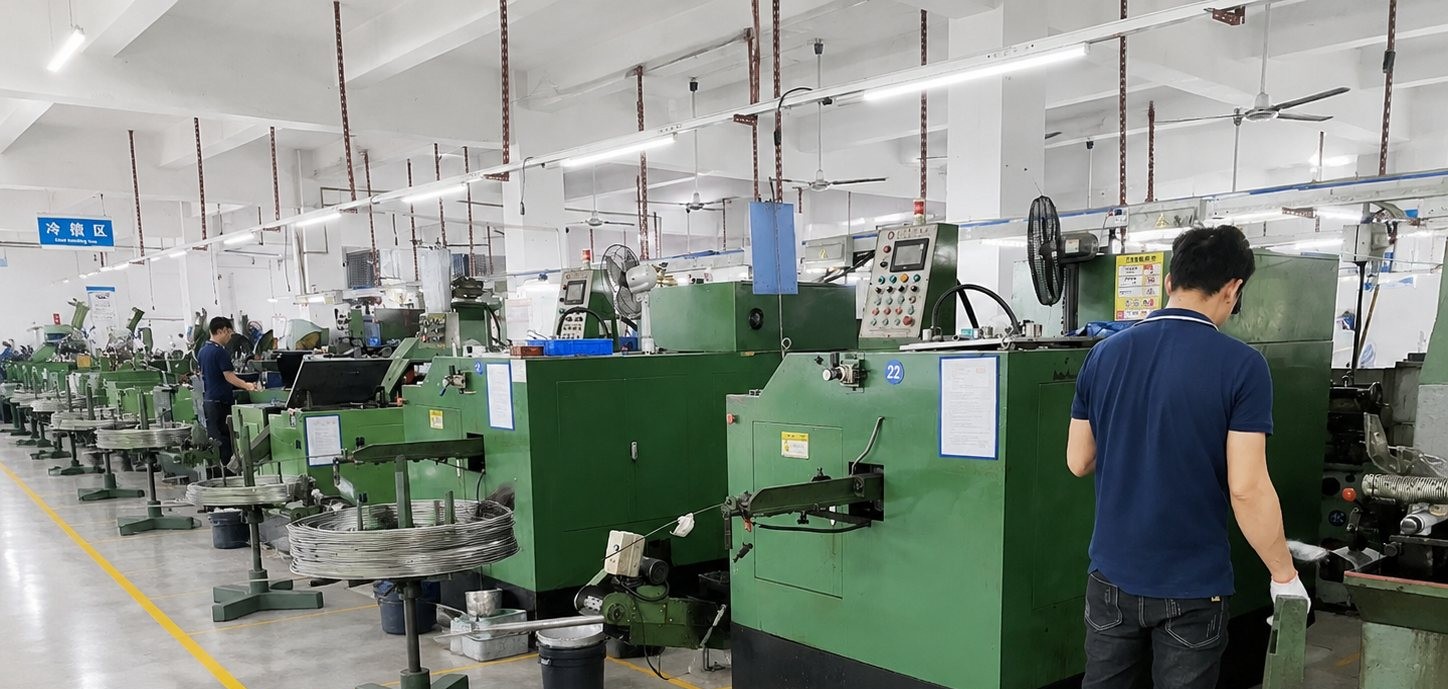
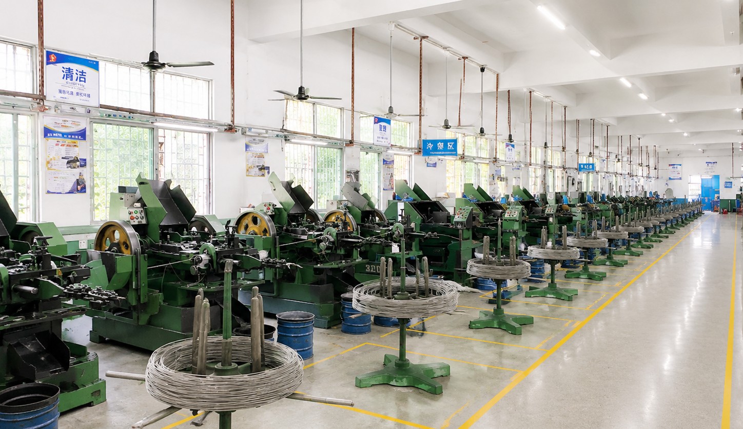
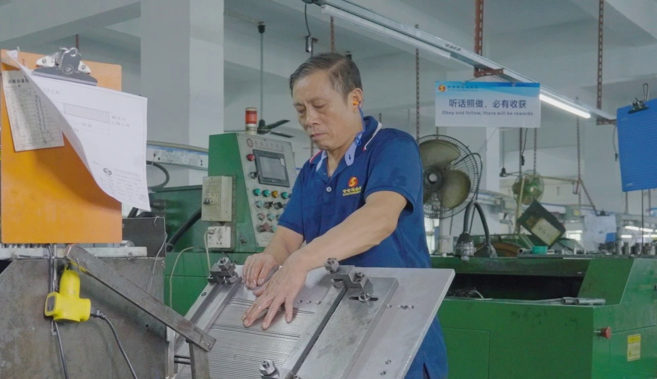
Shi Shi Tong turns these left hand thread machine screws from aluminium bar on CNC lathes: the head is turned and faced, the round bore is drilled and bored from the face, the shank is turned to the drawing diameter and the thread is cut left-hand with the spindle reversed. The parts are deburred, gauged and inspected before they leave the cell. The first part of every run is measured on the head, checked for bore concentricity and entered into a left-hand gauge before the batch continues.
|
|
The left-hand pass is where the setup shows. Running the spindle in reverse for the thread pass means the insert approaches the shoulder from the other side, so the tool clearance and the point where the thread ends at the shoulder are set at the first article and left alone. A thread that has been cut with the carriage travelling the wrong way looks right on the screw and will not enter the gauge, which is why the gauge check comes before the visual one.
What decides whether left hand thread machine screws pass is the hand of the thread, the bore, the head and the alloy. The inspection agreement covers those, and the criteria come from the drawing.
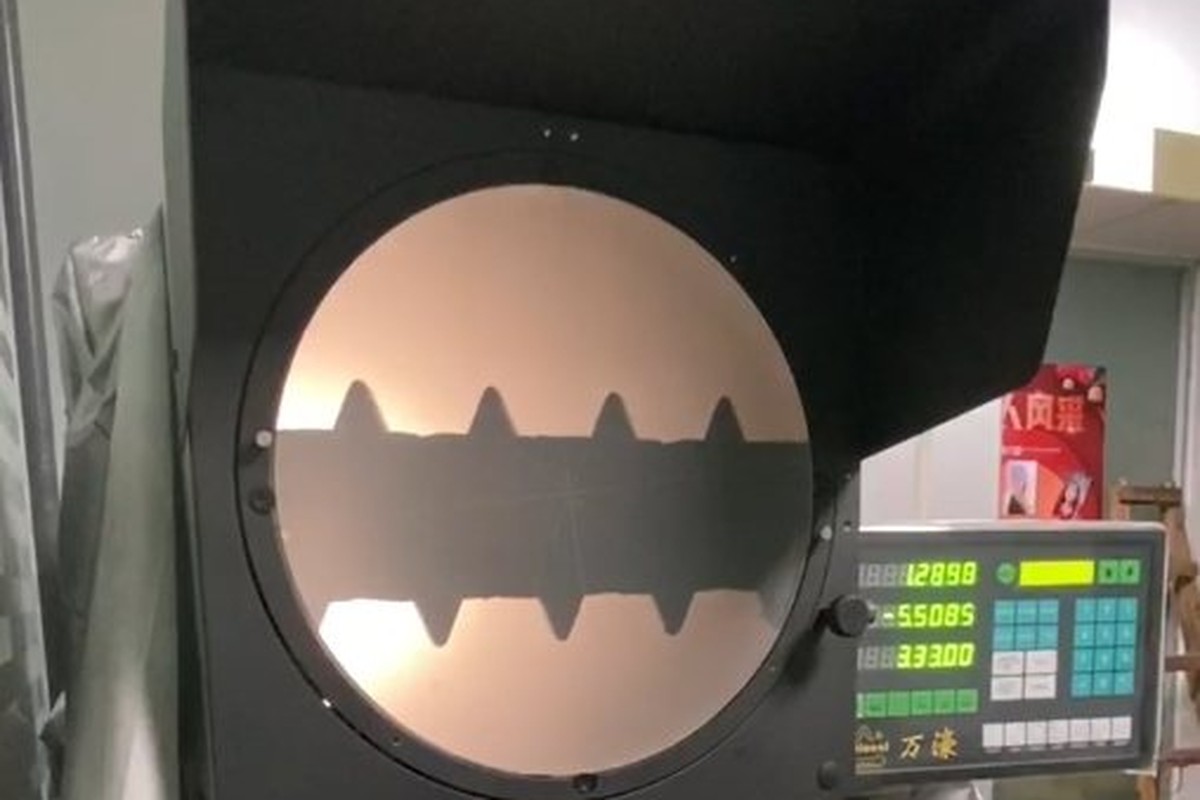
Head and bore on the projector |
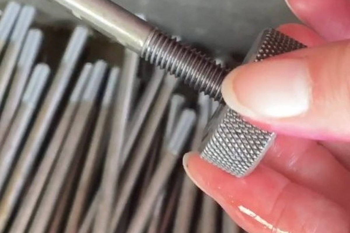
Thread checked with a left-hand gauge |
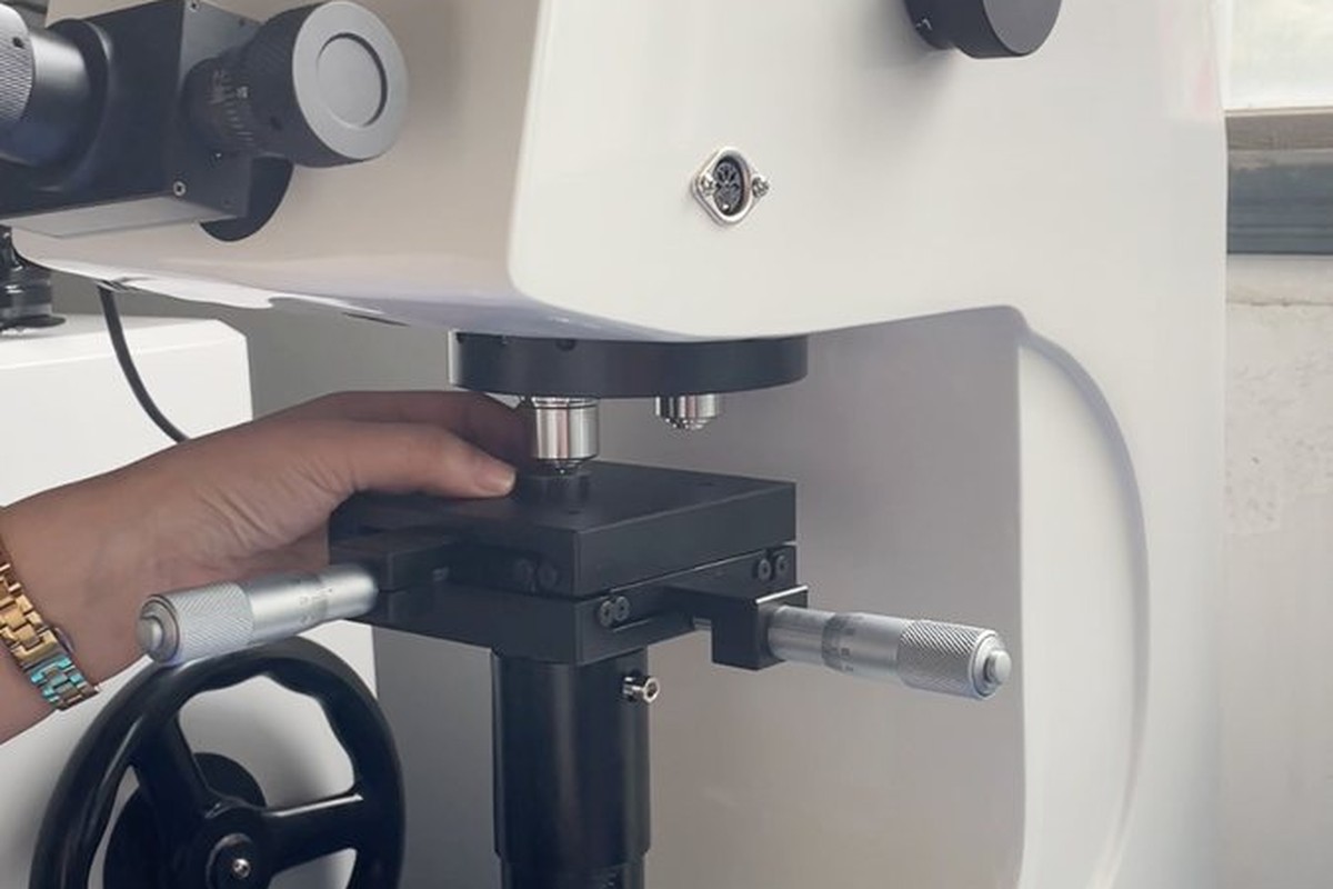
Hardness checked against the alloy temper |
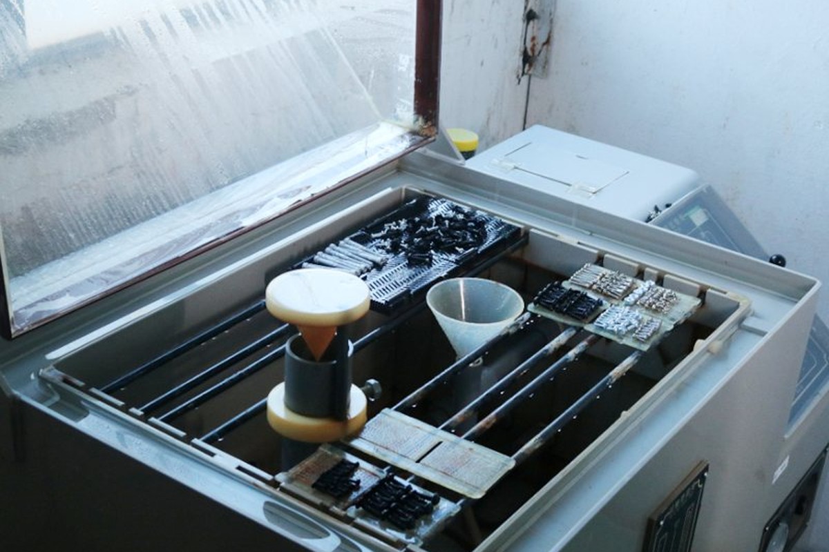
Salt-spray testing where a coating is specified |
The hand is checked first, with a left-hand GO gauge. A right-hand thread will start about one turn and then bind, so the check is quick and it is unambiguous: either the gauge runs the full thread or the part is rejected. On the first article the same check is repeated with the customer’s mating part, because a gauge and a nut can disagree about the last half turn.
The bore is checked on the optical projector for diameter, roundness and position relative to the shank. A bore that is round and the right size but off centre is the failure that shows up in the field rather than on the bench, because the screw drives, seats and then leans.
Hardness is checked on the bar and on the finished part, because the alloy and the temper decide how much torque the thread will take. A softer bar turns easily and strips early; a harder one cuts a cleaner thread and cracks at the shoulder if the corner radius is wrong. The two are read together.
Every shipment of left hand thread machine screws is traceable to the bar it was turned from. The alloy, temper and heat number are recorded on the material certificate supplied with the parts, and the inspection records follow the criteria agreed on the drawing.
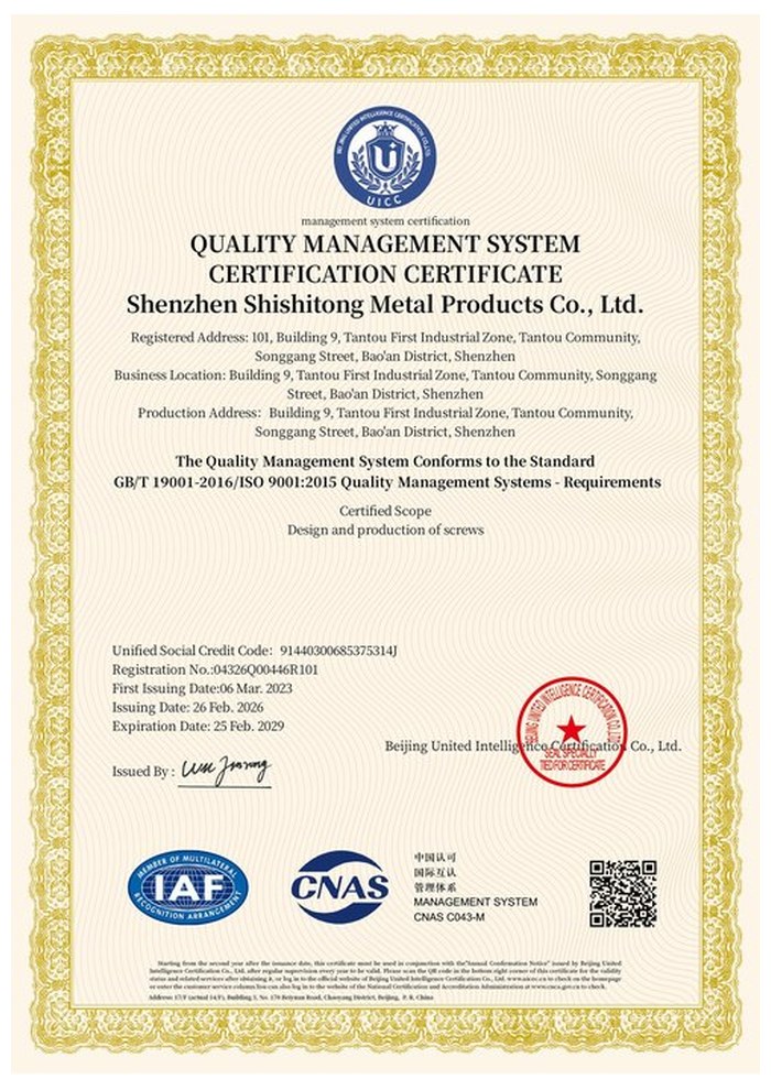
ISO 9001:2015 |
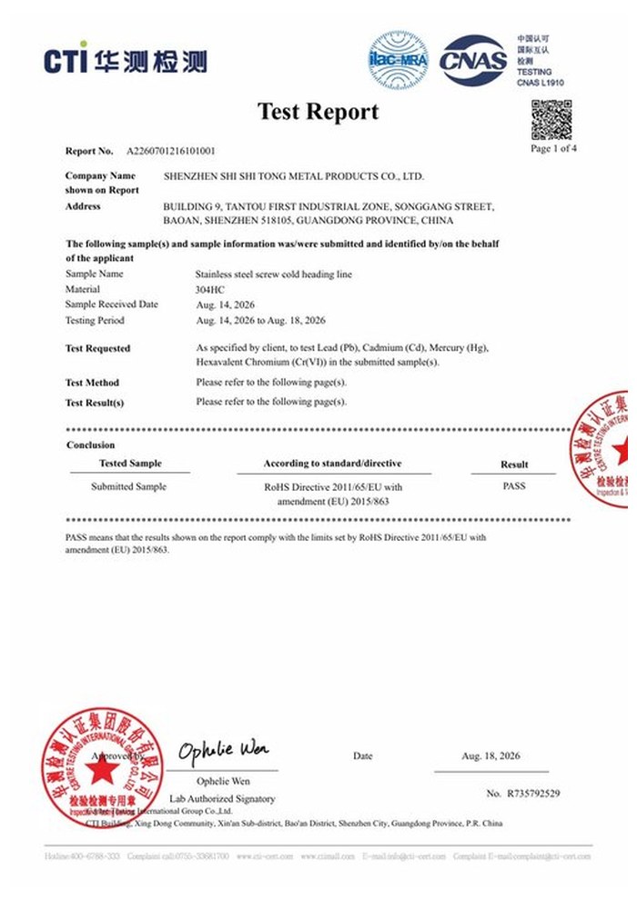
RoHS test report |
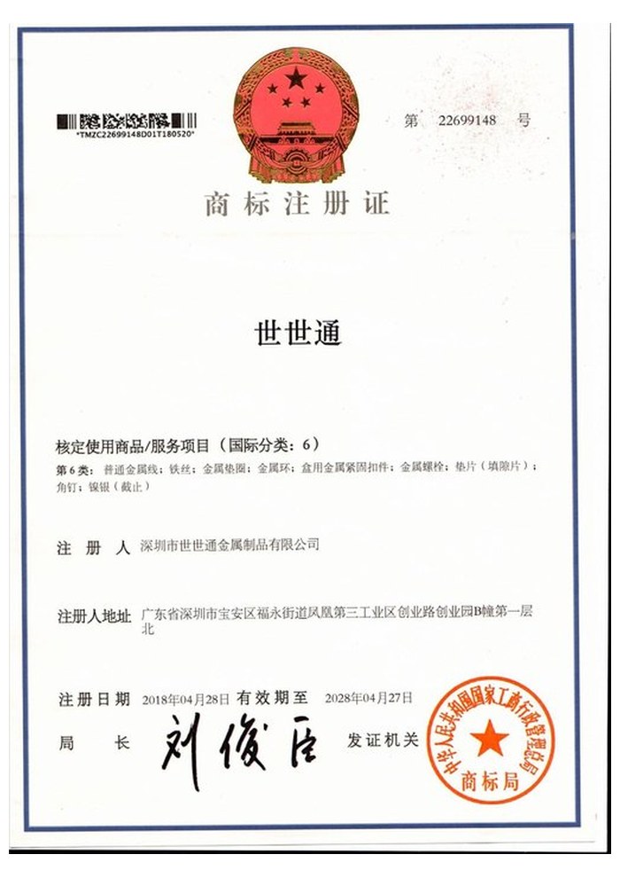
Registered trademark |
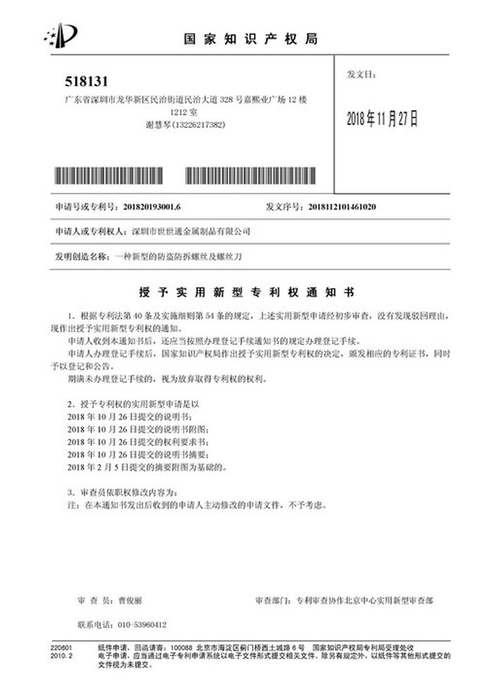
Patent: security screw and driver |
With each batch we supply the material certificate for the bar, the inspection record for the criteria on the drawing and, where it is listed, the third-party report for the alloy or the coating. The documents carry the drawing revision and the batch number, so the paperwork can be matched to the parts on the bench.
More than 8,678 customers in 89 countries and regions have ordered from Shi Shi Tong; 87% of orders come from repeat customers and 56% through referrals. Most projects follow the same route: drawing review, first-article approval, then batches checked against that sample. On a reversed thread the first article is also the point where the hand is agreed with the mating part, so it is approved as a working pair rather than as a screw on its own. Buyers visit during the process to review samples and to see how the threads are cut.
|
8,678+
customers served
|
87%
of orders from repeat customers
|
56%
of orders through referrals
|
89
countries and regions shipped to
|
Buyers and quality engineers visit for sample review, process discussion and supplier audits; the visit is arranged around production so the lathes and the gauging bench can be seen on the day the parts run.

Customer group visit – sample review |

Customer group visit – process discussion |

Customer group visit – factory tour |

Customer visit – project kick-off |

Danish customer – drawing review |
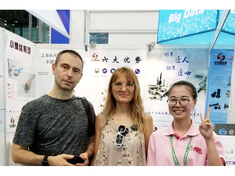
Industry exhibition – meeting customers |
Put a thread gauge on it: a left-hand gauge runs the full thread, a right-hand gauge starts about one turn and binds. On the bench it is the only check that settles the question.
So that the rotation of the part it holds tightens the joint instead of backing it out. It is chosen for hubs, arbors, one side of a pedal or crank, and adjusters that are turned in service.
No. The helix of a left hand thread machine screw and the one in the hole oppose each other, so the screw will start and then cross the thread. The tapped hole and the screw have to be the same hand.
A plain bore in the top face of the head instead of a cross or a hexagon. It needs its matching round-hole driver; other bits will spin in the bore and mark it.
Sooner than steel ones at the same size, because the alloy of a left hand thread machine screw is softer. Engagement length, torque and the mating material are set together on the drawing rather than taken from a steel table.
Thread size, pitch and hand, head diameter, bore diameter, thread and overall length with the datum, end form, alloy and temper, finish, and the acceptable thread engagement in the mating part.
How a left hand thread machine screw project runs from drawing to repeat delivery:
|
1
Send the drawing or the mating part
|
→ |
2
Hand and pitch reviewed
|
→ |
3
First article gauged and matched
|
→ |
4
Batch production and repeat orders
|
Each step is confirmed with you before the next one starts; the drawing revision from the first article is what repeat orders are checked against.
For a quotation, send the drawing with the thread size, pitch and hand, head and bore diameter, thread and overall length with the datum, end form, alloy and temper, and finish.
|
Thread, pitch, hand
|
Head diameter
|
Bore diameter
|
|
Length and datum
|
Alloy and temper
|
Finish
|
Sending a drawing? The form below does not take attachments. Email the PDF, DXF or STEP file to sst@szsst88.com with the part name and quantity in the subject line – the drawing is reviewed and a quotation follows.

 +86 13143444311
 sst@szsst88.com