Tel:
+86 13143444311
Email:sst@szsst88.com
Fax:+0086-755-27322278
Address:Building 9, First Industrial Zone, Tantou Industrial City, Songgang Street, Baoan District, Shenzhen 518105, Guangdong, China
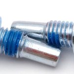
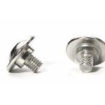
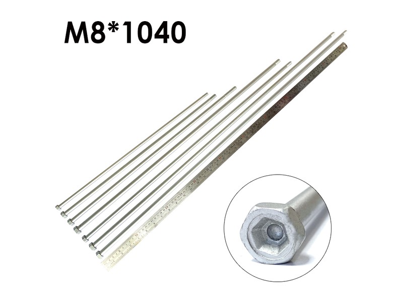
Type:Camera Screw Adapter
Materials:Aluminum
Surface treatment:plain
Head Type:ultra low head
Drive:Finger Flange
Thread:1/4-20 + 3/8-16 UNC
Features:Two Male Ends
Forming:Turned
Size:M1 M2 M3 M4 M5 M6 M7 M8 M9 M10 M14
Number:638
We turn camera screw adapters from aluminium bar with 1/4-20 UNC on one end and 3/8-16 UNC on the other, and a thin flange that grips and stops each end at its socket depth. Both thread lengths, the flange and the axis come from your drawing, and the first article is fitted to your camera and head.
Watch the factory video·Email sst@szsst88.com
ISO 9001:2015 · Manufacturing since 1998 · 8,678+ customers · 89 countries and regions
Made to order – there is no stock catalogue. Each part is produced to your drawing, and production starts after drawing review and first-article approval.
A camera screw adapter is the short stud that lets a 1/4-20 camera mount and a 3/8-16 head or plate work together, threaded one size on each end with a thin flange between them. The recorded item is aluminium with a plain finish and an ultra low flange, turned from bar and quoted from M1 to M14 with Number 638.
Two threads, one part. One end is 1/4-20 UNC, the size in the bottom of almost every camera; the other is 3/8-16 UNC, the size on large heads, fluid heads and studio plates. The adapter is the translation between them.
Ultra low flange. A thin shoulder between the two threads. It gives the fingers something to grip when fitting, and it acts as a depth stop so neither end goes further than it should into its socket.
Turned from aluminium. Light, and it machines a clean thread on both ends in one setting, which is what keeps the two threads on the same axis. Plain finish, so both threads are exactly as cut.
A camera screw adapter is a stud, and the whole difficulty is in the two ends. Each has a different thread, and both have to be concentric with the other or the camera sits at an angle on the head. Turning it in one setting is what guarantees that: the bar is set up once and both threads are cut against the same axis, so the runout of one end relative to the other is a fraction of the tolerance the joint needs.
The flange does three jobs at once. It is the grip, because a stud with no head cannot be tightened by hand; it is the depth stop, because each end has to engage a socket of a defined depth and no more; and it is the bearing face, because it is what presses against the camera base or the plate when the adapter is snug. On a camera screw adapter quoted as ultra low, the flange is thin enough that the camera still sits on the head’s own surface, not on the adapter.
On a camera screw adapter the thread lengths are the dimensions that cause damage. An end that is longer than the socket it goes into bottoms out, and from that point the adapter lifts the camera rather than pulling it down. The other end has to be long enough to engage its socket fully, because a thread that only catches a couple of turns will pull out under the weight of a lens.
Aluminium is the usual material for the reasons that matter here: it is light, it cuts a clean fine thread, and it does not gall against steel as readily as stainless does. What it does not do is forgive an over-tightened adapter — the flange is thin, and a flange crushed by a hand-plus-tool will no longer hold the socket clear of the surface.
Pound for pound, the plain finish is the right one. There is nothing to chip at the flange where it bears, and nothing to fill either thread, so the adapter that arrives is the adapter that keeps fitting whatever head the customer bought later.
The family is quoted from M1 to M14 for metric variants, with the camera sizes cut to 1/4-20 UNC and 3/8-16 UNC. Custom lengths up to 2,000 mm are subject to DFM review after drawing submission; on a camera screw adapter each thread length and the flange thickness are quoted separately, because each has its own socket to fit.
| Item | How it is defined | What we control |
|---|---|---|
| Thread A | 1/4-20 UNC, length from the end | Pitch and length, gauged |
| Thread B | 3/8-16 UNC, length from the end | Pitch and length, gauged |
| Flange | Thin shoulder between the threads | Thickness, diameter and squareness |
| Axis | Both threads concentric to each other | Checked on the projector at the ends |
| Finish | Plain aluminium | Threads clean, no burrs at the flange |
| Overall | End to end | Measured on the shop plate |
The two thread lengths are quoted independently from opposite ends, never as one overall figure. An overall length tells the customer nothing about whether either end will bottom in its socket, and the sockets on a camera and on a plate are different depths.
Flange thickness is the dimension that decides whether the joint is solid. Too thick and the camera sits on the adapter rather than on the plate, so the joint is a small ring instead of a face; too thin and the flange deforms when the adapter is tightened, and the thread then sits at an angle.
Three features define a camera screw adapter: the two threads, the flange and the single axis. Together they mean the adapter either works invisibly — the camera sits square and the thread stays put — or it introduces an error that shows up in every shot.
| Feature | What it gives | What it costs |
|---|---|---|
| 1/4-20 and 3/8-16 | Two mounting standards joined | Two thread lengths to control |
| Thin flange | Grip plus a depth stop | Thin section that deforms if over-tightened |
| Turned in one setting | Both threads on one axis | A lathe operation per part |
| Plain aluminium | Light, no coating in the thread | Soft; galls if forced into steel |
| Short overall length | Keeps the camera close to the plate | Very little material for the flange |
The failure that matters is a camera that is no longer square to the plate. An adapter with the two threads slightly out of line stands the camera off at an angle, and on a long lens that angle is visible as a tilted frame that no amount of levelling fixes, because the error is in the joint rather than the head.
The second failure is the adapter left in the camera. It is a small part, it is easy to forget, and when it is removed with the wrong tool the thread comes out the harder way. A plain aluminium adapter in a steel socket will gall if it is forced, and then the camera thread is the thing that suffers.
Camera screw adapters are finished plain, in aluminium. There is no anodising, so both threads are exactly as cut and the flange keeps the edge that gives it grip. Anodising would add a few microns to a thread that has to fit a camera socket, and on a 1/4-20 that is measurable.
| Option | How it protects | Effect on threads and flange | Typical use |
|---|---|---|---|
| Plain aluminium | Natural oxide film | None; threads as cut | General adapters |
| Anodised aluminium | Grown oxide, dyed | A few microns; threads re-checked | Colour-coded or wear-resistant |
| Stainless, plain | Passive chromium oxide film | None; threads as cut | Heavy or marine rigs |
| Brass, plain | Natural oxide, conductive | None; threads as machined | Where weight is not critical |
| Steel, black oxide | Conversion film, oiled | No measurable build | Rare; heavier than needed |
The choice is mostly about weight and galling. Aluminium is the lightest and the least likely to seize in a steel socket; stainless is the most corrosion resistant and the most prone to galling against itself; brass sits between them and is easy to machine but heavier.
Where the adapter is anodised, the thread has to be checked afterwards, because a few microns in a 1/4-20 changes the fit and the adapter either will not start or starts and binds. That is why plain is the default on a part whose only job is to screw into two other things.
Three places where a camera screw adapter is the fixing:
| Where it sits | The adapter joins a camera’s 1/4-20 socket to a 3/8-16 head or plate, where the head is built for a larger thread and the camera is not. |
| When it goes wrong | A thread that bottoms in the camera socket lifts the camera, and one that is short engages too few turns for a heavy lens. |
| Why it happens | The two standards differ, the load is a camera and lens, and the joint is made and broken often. |
| What we control | Both thread lengths checked against sample sockets, flange thickness and axis verified. |
| Where it sits | The adapter fits a light stand, a clamp or a boom to a camera or a small head where the threads differ and the joint has to hold a lever arm. |
| When it goes wrong | An off-axis adapter tilts the load, and a thin flange deforms under a boom’s weight. |
| Why it happens | The rig carries a lever arm, the joint is tightened by hand, and the parts are handled daily. |
| What we control | Axis checked on the projector, flange and thread gauged per batch. |
| Where it sits | The adapter mounts a camera or an adapter tube onto a stand or a plate where the threads are the camera standard and the alignment matters. |
| When it goes wrong | Any runout between the two threads shows as a tilted field of view, and a soft aluminium adapter can be crushed by a spanner. |
| Why it happens | The mount is fixed, the alignment is functional, and the adapter stays in place. |
| What we control | Axis and flange squareness checked, both threads gauged. |
Four reasons that matter on camera screw adapters, each tied to what the drawing has to prove:
|
Both threads and the flange reviewed together
Each thread length, its socket depth and the flange thickness are reviewed as one set, so an end that would bottom or a flange that would lift the camera is raised before the bar is cut. Basis: Both threads and the flange reviewed as one set. |
Turned on one axis
The adapter is turned in one setting so both threads share an axis, which is what keeps the camera square on the head. Basis: One setting, one axis. |
|
Both ends measured and tried
Both threads are gauged and the adapter is run into sample sockets at each end, and the axis is checked on the projector. Basis: Both ends gauged and fitted to sample sockets. |
First article fixes the setting
The first article fixes the alloy, the program and the thread passes; repeat orders are compared against that record. Basis: First article signed off before the batch is released. |
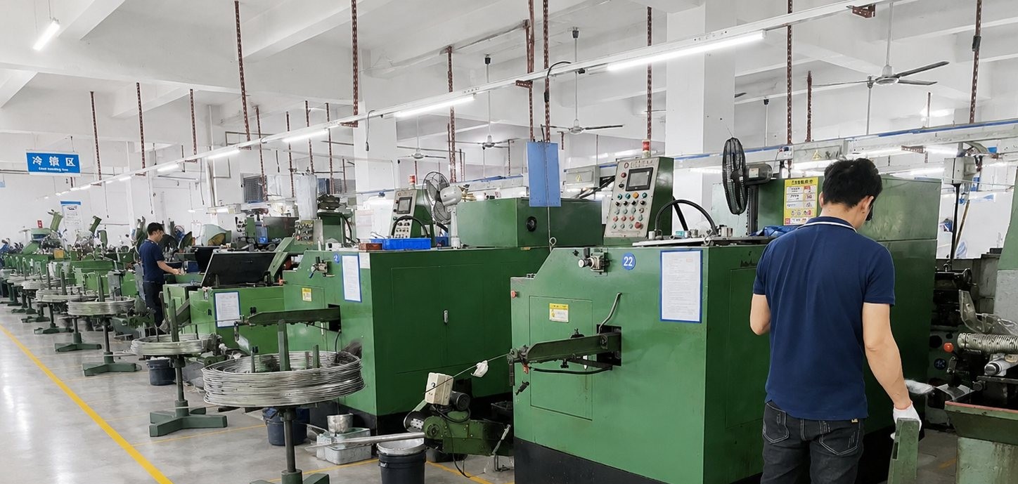
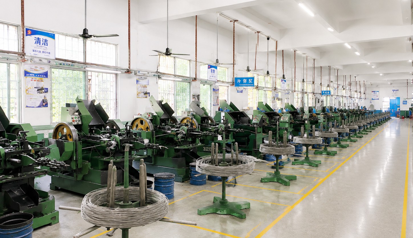
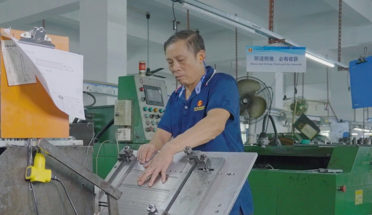
Shi Shi Tong turns these camera screw adapters from aluminium bar in one setting: the outside is turned, the flange is faced to thickness, and both threads are cut to their own length from opposite ends without the part leaving the chuck. The bores and chamfers are deburred, the parts are cleaned and inspected, and the first article is run into sample sockets at both ends.
|
|
Turning both threads in one setting is the whole process argument. If the part is turned round between operations, the second thread is cut against a fresh datum and the two ends can end up a few hundredths out of line; the adapter then tightens, but the camera sits at an angle that shows in the frame.
What decides whether camera screw adapters pass is both threads, the flange, the axis and the alloy. The inspection agreement covers those, and the criteria come from the drawing.
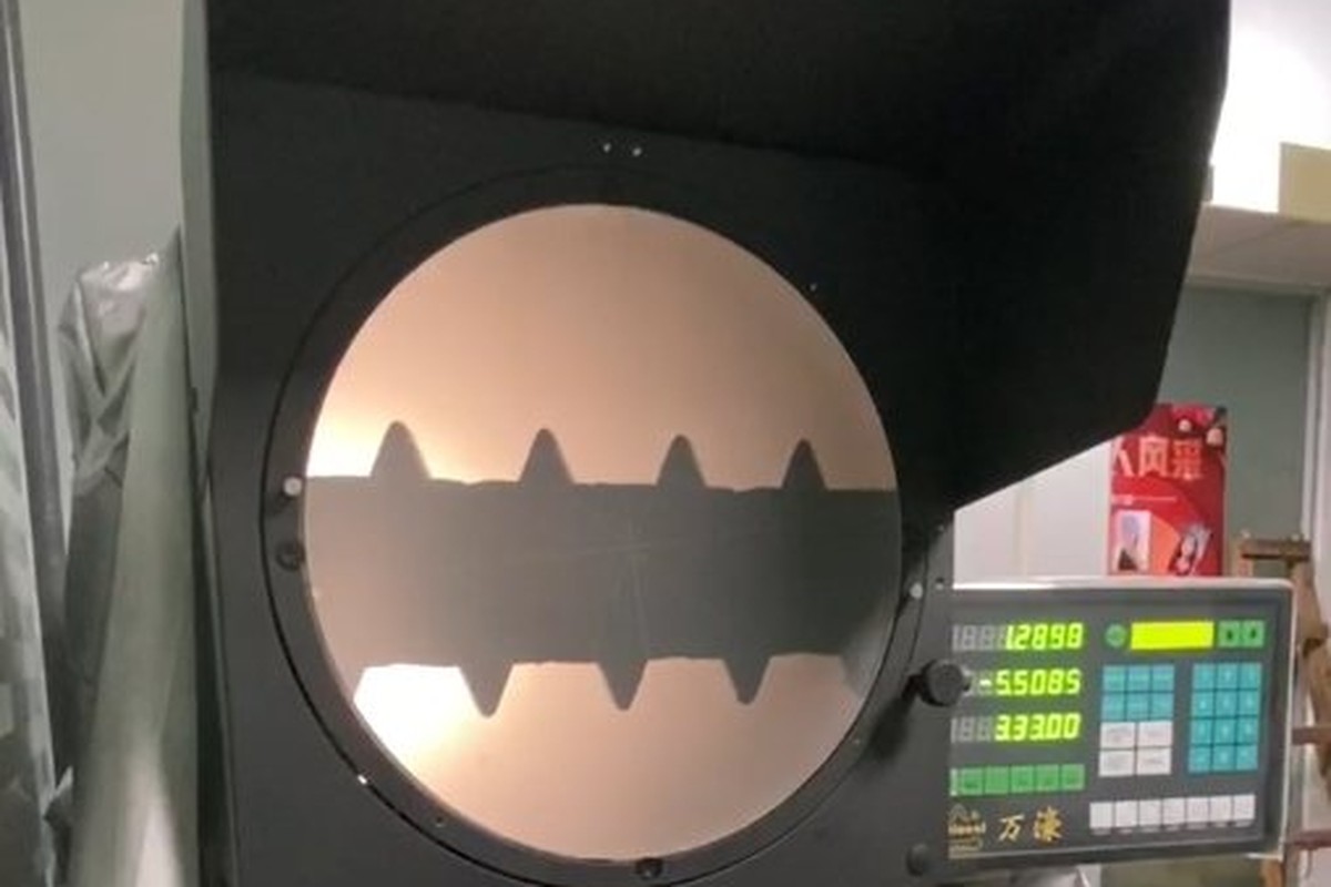
Flange and threads on the projector |
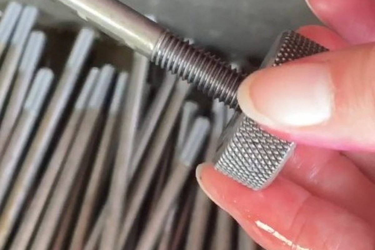
Both threads gauged |
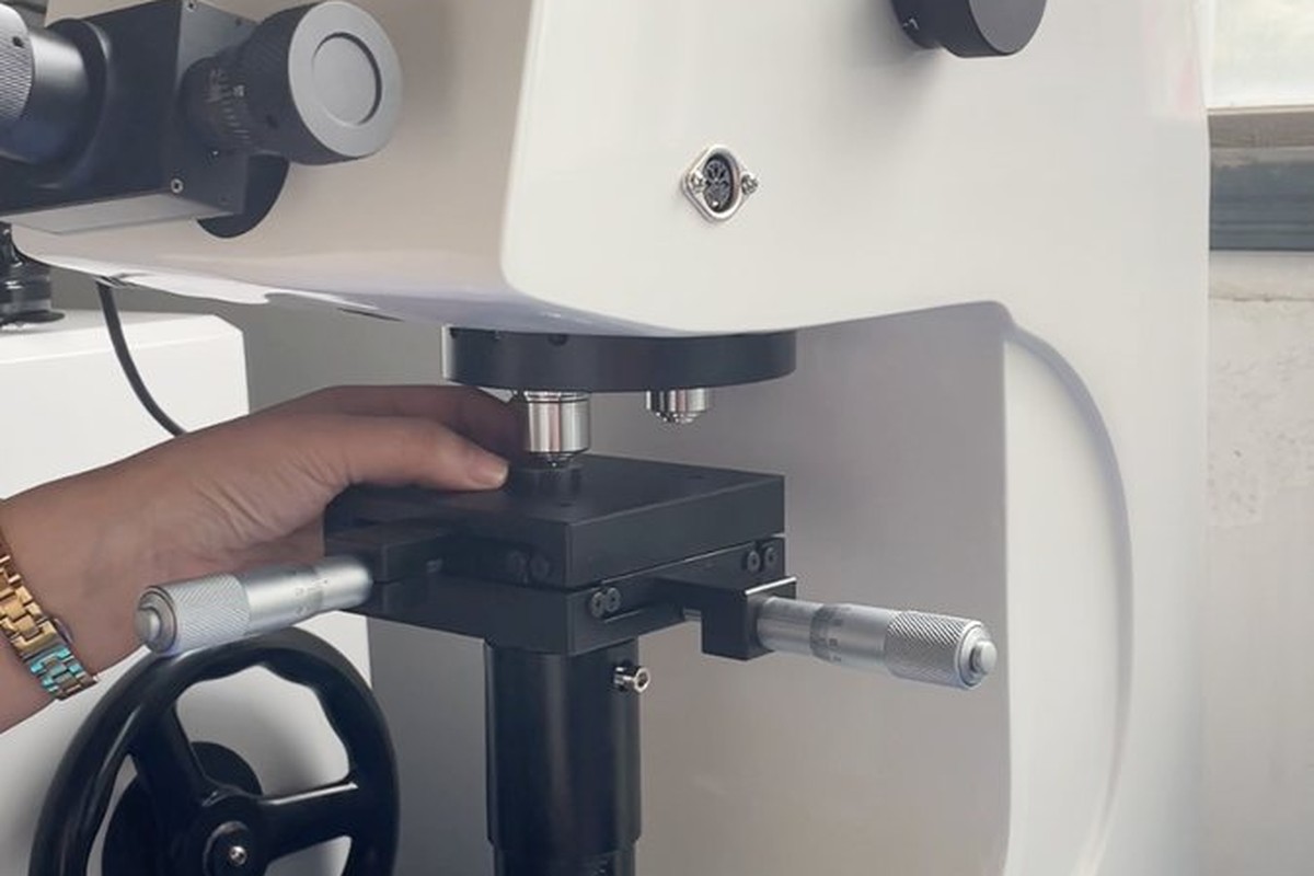
Hardness checked against the alloy |
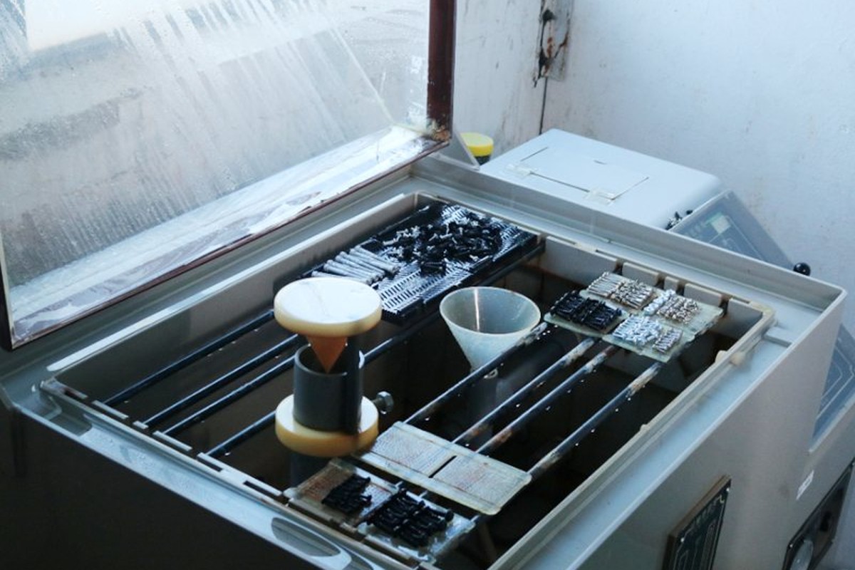
Salt-spray testing where a coating is specified |
On a camera screw adapter both threads are gauged, and each end is run into a sample socket of the size it will meet. The socket is the check that matters, because a thread can pass a gauge and still bottom in a shallow socket — and bottoming is the failure that lifts the camera.
The flange is checked for thickness, diameter and squareness, and the axis is checked on the projector by reading runout at both ends. On an adapter the axis is a functional dimension even though it is not drawn as one: it is what keeps the camera square.
Every shipment of camera screw adapters is traceable to the bar they were turned from. The alloy, temper and heat number are recorded on the material certificate supplied with the parts, and the inspection records follow the criteria agreed on the drawing.
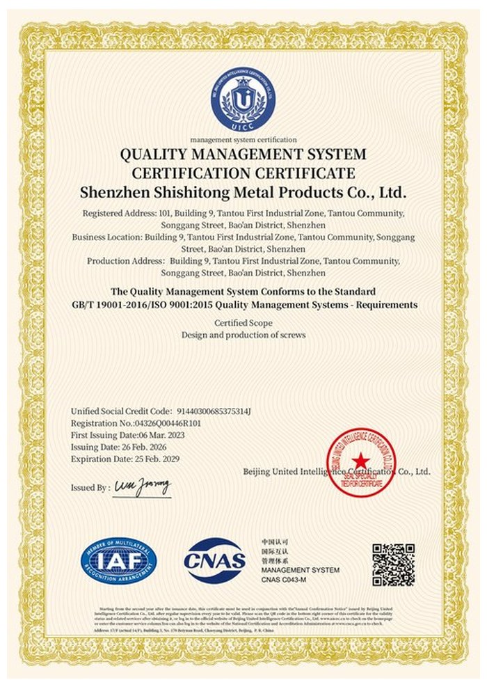
ISO 9001:2015 |
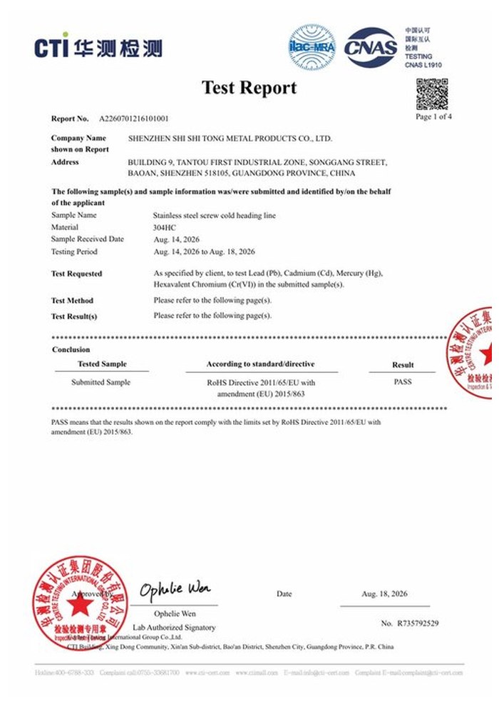
RoHS test report |
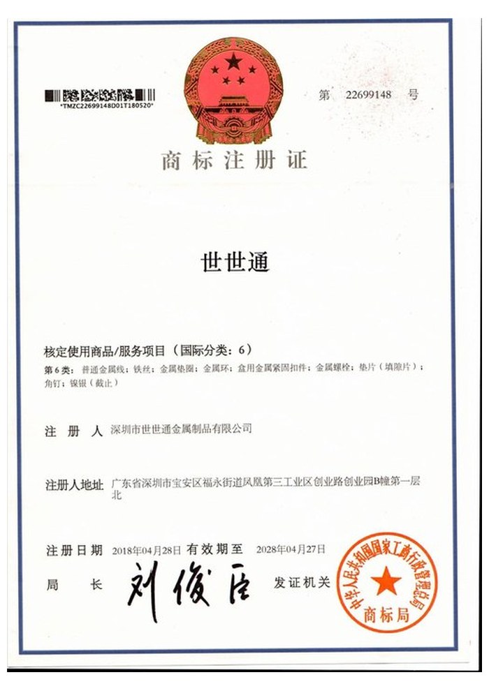
Registered trademark |
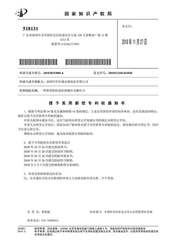
Patent: security screw and driver |
With each batch we supply the material certificate for the bar, the inspection record for the criteria on the drawing and, where it is listed, the third-party report for the alloy or the coating. The documents carry the drawing revision and the batch number, so the paperwork can be matched to the parts.
More than 8,678 customers in 89 countries and regions have ordered from Shi Shi Tong; 87% of orders come from repeat customers and 56% through referrals. Most projects follow the same route: drawing review, first-article approval, then batches checked against that sample. On an adapter the first article is also fitted to the customer’s own camera and head, because the two sockets are the real tolerances. Buyers visit during the process to review samples and to see how the parts are turned.
|
8,678+
customers served
|
87%
of orders from repeat customers
|
56%
of orders through referrals
|
89
countries and regions shipped to
|
Buyers and quality engineers visit for sample review, process discussion and supplier audits; the visit is arranged around production so the lathes and the inspection bench can be seen on the day the parts run.
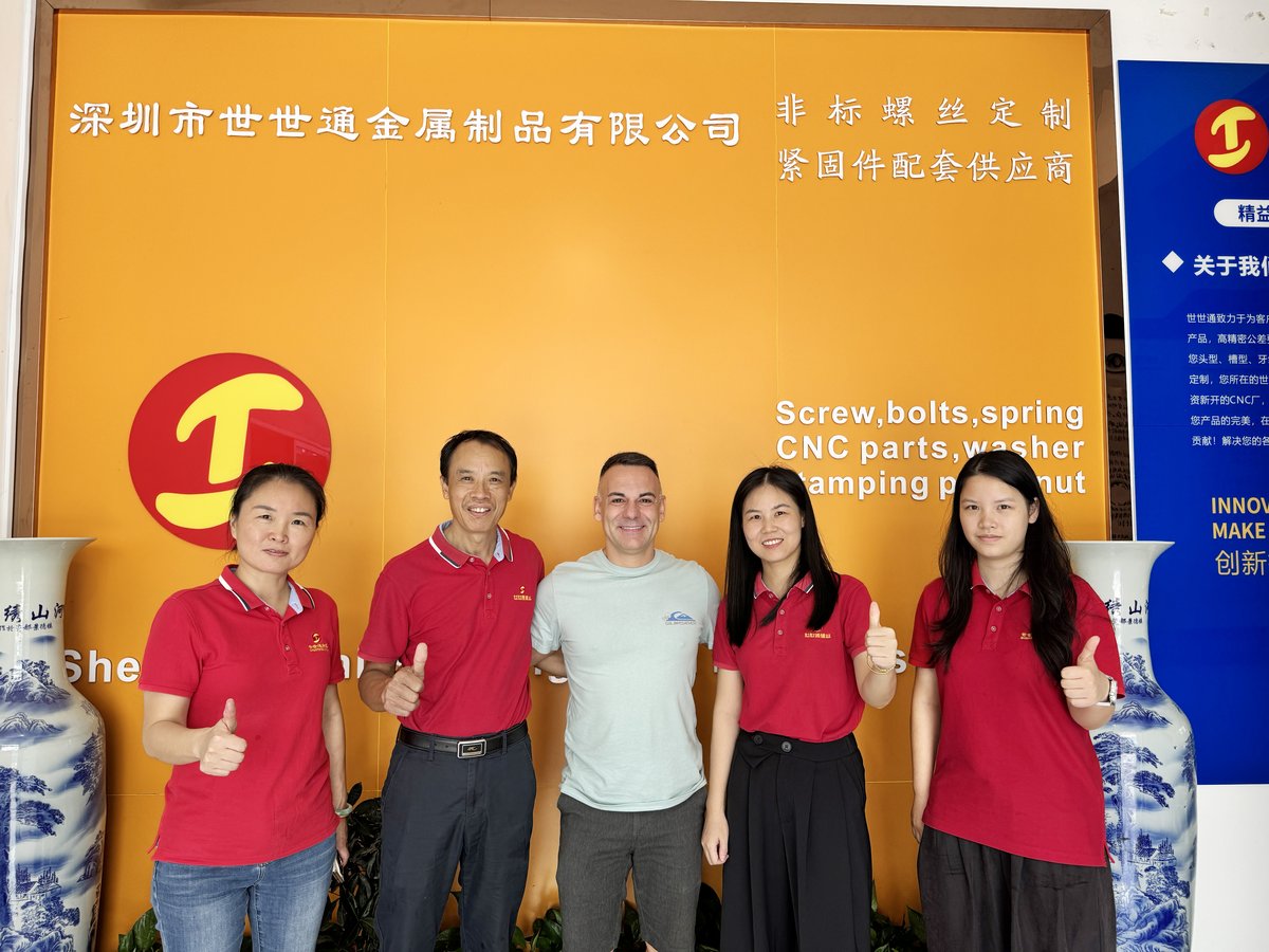
Customer group visit – sample review |

Customer group visit – process discussion |
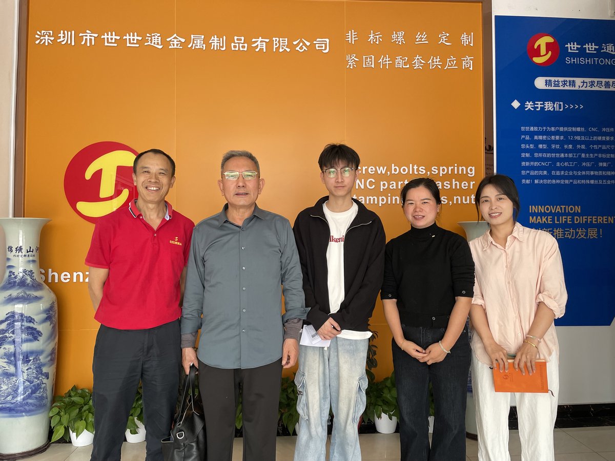
Customer group visit – factory tour |

Customer visit – project kick-off |
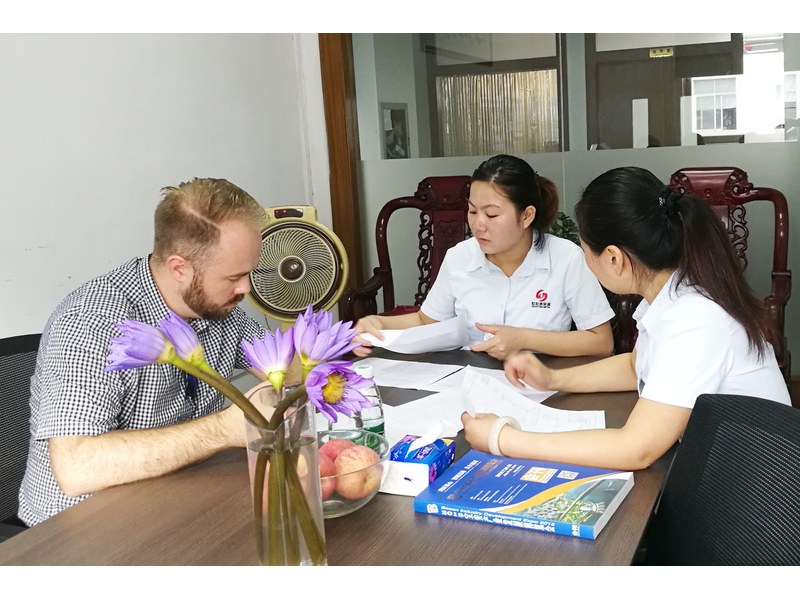
Danish customer – drawing review |
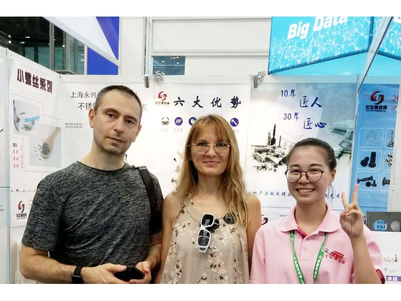
Industry exhibition – meeting customers |
It joins two mounting standards: 1/4-20 UNC on most cameras and 3/8-16 UNC on large heads and plates. One end threads into each.
Each socket has a depth. An end that bottoms lifts the camera instead of pulling it down, and one that is short engages too few turns for a heavy lens.
So the camera still sits on the plate rather than on the adapter. A thick flange becomes the bearing face and the joint rests on a small ring.
No. The flange is thin aluminium and it deforms. It is fitted by hand, and the joint it makes is only as good as the two threads.
Aluminium in a steel socket can gall if it is forced. Fit by hand, and remove the adapter before storing the camera if the rig is used that way.
Both thread sizes with their lengths from the ends, the flange diameter and thickness, the overall length, the alloy and the finish.
How a camera screw adapter project runs from drawing to repeat delivery:
|
1
Send the drawing and the two sockets
|
→ |
2
Both thread lengths and the flange review
|
→ |
3
First article fitted at each end
|
→ |
4
Batch production and repeat orders
|
Each step is confirmed with you before the next one starts; the drawing revision from the first article is what repeat orders are checked against.
For a quotation, send the drawing with both thread sizes and their lengths from the ends, the flange diameter and thickness, the overall length, the alloy and the finish.
|
Thread A and length
|
Thread B and length
|
Flange diameter
|
|
Flange thickness
|
Overall length
|
Alloy
|
Sending a drawing? The form below does not take attachments. Email the PDF, DXF or STEP file to sst@szsst88.com with the part name and quantity in the subject line – the drawing is reviewed and a quotation follows.

 +86 13143444311
 sst@szsst88.com