Tel:
+86 13143444311
Email:sst@szsst88.com
Fax:+0086-755-27322278
Address:Building 9, First Industrial Zone, Tantou Industrial City, Songgang Street, Baoan District, Shenzhen 518105, Guangdong, China
Type:White Machine Screws
Materials:Steel
Surface treatment:White Zinc Plated
Head Type:Low Profile Head
Size:M1 M2 M3 M4 M5 M6 M7 M8 M9 M10 M14
Number:115
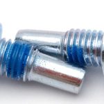
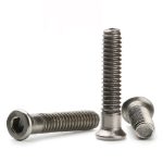
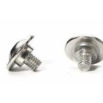
This is a custom turned part rather than a catalogue machine screw. A thin flat head with a single slot across its full diameter sits on a smooth unthreaded shoulder; the shoulder ends in one wide integral collar whose flat face is the bearing surface; past the collar there is only a short length of machine thread and a blunt chamfered tip. It is turned from carbon steel and finished in white zinc.
That combination is deliberate. The plain shoulder is the locating diameter — a bracket, a cover, a hinge leaf or a clevis pivots or slides on a turned cylinder instead of on a thread crest — while the collar stops the part axially and spreads the clamping load over a face far larger than the head. The short thread does one job only: it clamps. Everything else in this page follows from those three decisions, including why the head is so thin and why the slot, not a cross recess, is the drive.
|
Material
Carbon steel
|
Finish
White zinc, trivalent passivation
|
Head
Low-profile flat, turned
|
Drive
Single slot, full head diameter
|
|
Shoulder
Plain, unthreaded
|
Collar
Integral flange, flat bearing face
|
Thread
Machine thread, short length
|
Tip
Blunt, small chamfer
|
|
Size range
M1 – M14
|
Process
Turned from bar stock
|
Tolerance
To drawing
|
Packing
Bulk or bagged to agreement
|
Values above describe the family this page covers. Actual head diameter, head thickness, shoulder diameter and length, collar diameter, thread size and thread length are set per drawing on the order.
There is one slot and nothing else. No cross recess, no hex socket, no external flats — so the entire tightening torque passes through two thin ribs of material on either side of the slot. On a head this thin that is the governing limitation of the part, and it decides how the head is dimensioned: the slot has to be deep enough to hold a blade without camming out, and shallow enough to leave a load-bearing web under it.
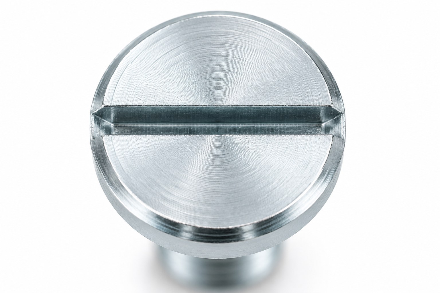
The slot runs the full head diameter and is milled after turning, so its floor is flat and its mouth breaks the head chamfer cleanly. The faint concentric marks on the face are turning marks from the same set-up that faced the head.
A slotted drive is chosen here for field service, not for torque density. A flat blade is the one tool that is always present on a panel, a cabinet or a machine guard, and it self-cleans in a painted or dusty environment where a cross recess fills with debris. The trade is that blade fit has to be controlled: a blade narrower than the slot concentrates load on two lines and rounds the slot mouth, and a blade that is too thick bottoms out and lifts the driver off the head.
Between the head and the collar there is no thread at all. This is the functional diameter of the part. If the screw passes through a bracket hole sized to the shoulder, the bracket is located on a ground-turned cylinder with a known clearance, and it can rotate around the screw axis — a pivot — or slide along it, without the thread crests acting as a reamer on the hole.
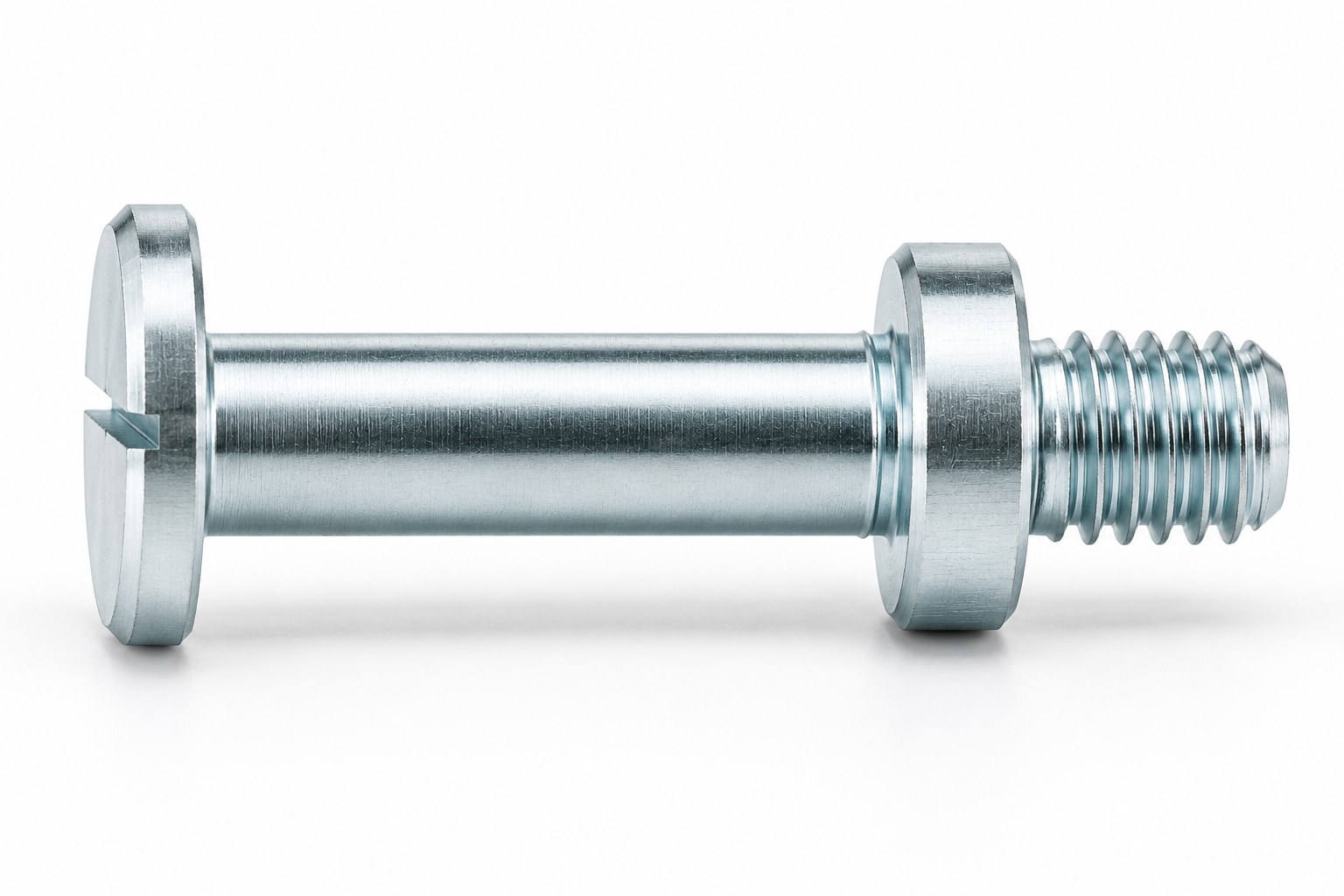
Head, shoulder, collar and thread are turned on one axis. The thread occupies only the last short section; the long plain cylinder in the middle is the locating surface.
The consequence is a rule we apply to every drawing of this type: hole tolerance and shoulder tolerance are agreed together, because the running fit of the joint is the difference between them. Thread length is then kept short on purpose. A long thread on a shoulder screw adds nothing to clamp force and takes away locating length, and it puts thread runout inside the bearing area where it will eventually wear the hole.
The collar is not a washer and it is not a decorative flange. It is turned from the same bar as the shoulder, so its face is square to the axis by construction rather than by assembly, and it is the surface that lands on the part being clamped. Under torque it converts a point load at the head into a ring load around the hole, which is what keeps thin sheet, plastic and anodised aluminium from cupping or cracking.
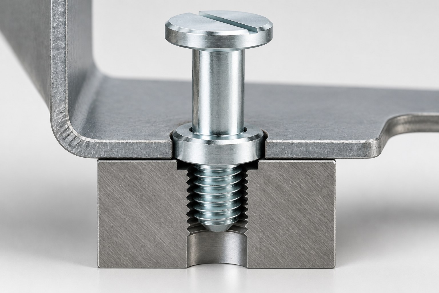
The collar face seats on the bracket; the shoulder passes through the clearance hole; the short thread engages below. The bracket is located by the shoulder, not by the thread.
Because the collar face is the datum, it is also the surface we inspect first. Face-to-axis squareness shows up as a rocking joint long before any dimension goes out of tolerance, and on a turned part it comes from one thing: whether the face was cut in the same set-up as the shoulder. Re-chucking the part to face the collar afterwards is the usual way a good-looking batch develops a wobble.
Thread runout is where a shoulder screw is usually lost. If incomplete thread creeps under the collar face, the collar no longer lands flat — it lands on the last, incomplete turn — and the joint loses squareness by exactly the height of that partial thread. The thread therefore has to end in a clean runout below the collar, with the full-form thread starting only where the drawing allows it.
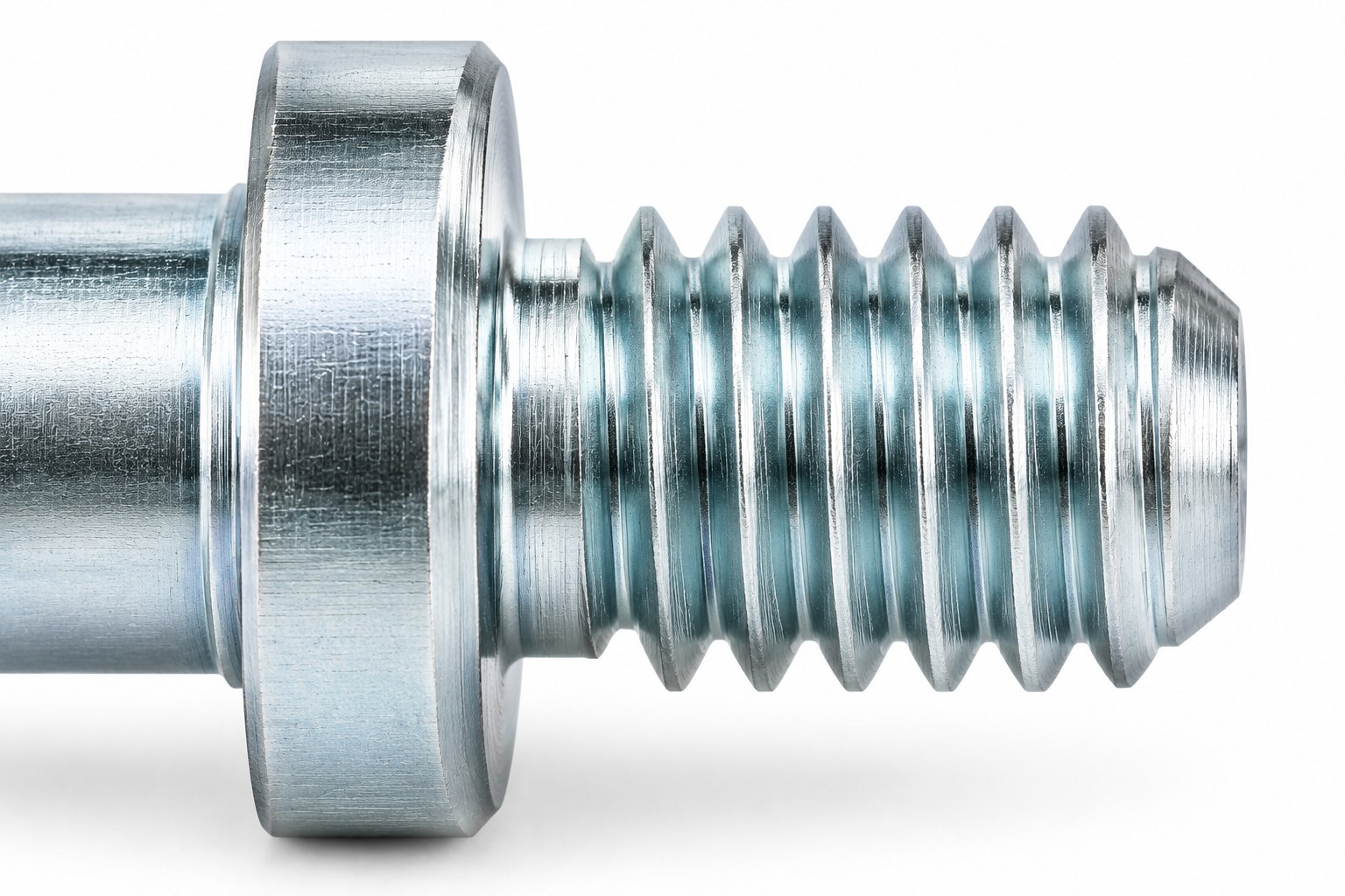
Short machine thread, full form up to the collar, blunt chamfered tip. The tip is chamfered rather than pointed so it can find a tapped hole without cross-threading it.
The blunt chamfered tip is part of the same logic. A pointed or dog-point end is a locating feature and would be wrong here; a chamfer leads the thread into the tapped hole and leaves a flat end face that will not score a painted panel if the screw is ever run in without a mating part behind it.
On this screw the three dimensions that matter most are not independent, and that is the single most important thing to understand before quoting or inspecting it. Head thickness, slot depth and collar face position all sit on one axial stack cut from the same bar. The head is faced, the slot is milled into that faced surface, and the collar face is turned from the same stock — so removing material for the slot and correcting the head face both change the distance from the slot floor to the collar bearing face.
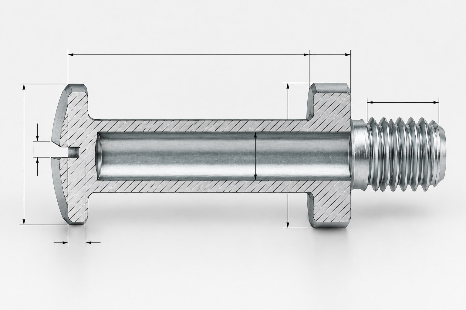
In section, the wall between slot floor and collar face is the thinnest part of the load path. Slot depth is set against head thickness, never the other way round.
Practically, this means the slot depth cannot be specified on its own. Deepen the slot by 0.1 mm and either the head grows or the web under the slot thins; face the head afterwards and the slot becomes shallower than the drawing says. The same stack also fixes the assembled height: for a given panel thickness and shoulder length, the distance from the collar face to the top of the head is what the customer’s stack-up calculation uses, and it moves with every one of those operations. We hold the stack as one dimension chain and inspect a sectioned sample, not three separate numbers.
A second, smaller relation lives in the same area: the slot mouth breaks the head chamfer. If the chamfer is cut after the slot, it re-cuts the slot edges and widens the effective blade opening; if it is cut before, the slot edges stay sharp and can cut the operator’s blade or a painted surface. The order is fixed in our process sheet for exactly this reason.
White zinc is a thickness, not a colour. It is deposited on every surface the electrolyte reaches, which on this part includes the slot walls, the slot floor, the collar face and the thread flanks. Every one of those surfaces has a fit on it: the slot has a blade, the thread has a tapped hole and a GO / NO-GO gauge, and the collar face has the part it clamps. Plating moves all of them.
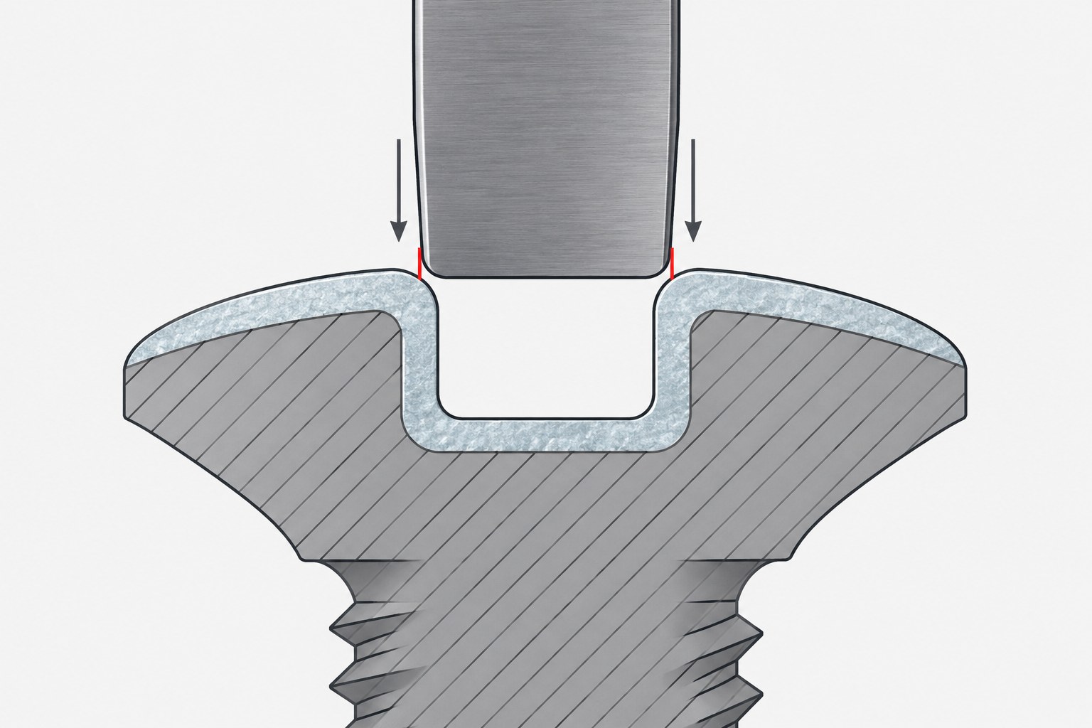
Plating thickness is exaggerated here to show the effect: the layer closes the slot by roughly twice its thickness and rounds the slot mouth. Slot width and thread limits are therefore specified after plating.
The rule we work to is simple: slot width, thread limits and any critical diameter are specified as plated dimensions. The screw is gauged after plating, not before, because a part that passes a GO gauge before the barrel and fails it afterwards has still failed. For thin heads there is a second effect — build-up on the slot mouth rounds the edge the blade bears on, which changes where the driver sits and how much torque the slot will take before it deforms.
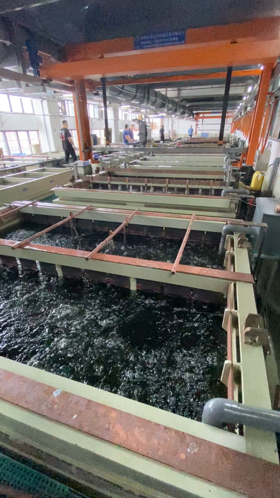
Barrel plating in-house, with the plating thickness and the post-plating gauge check recorded per lot.
Carbon steel brings one more control into scope. Acid pickling and plating charge the steel with hydrogen, and a hardened or high-strength part can fail later under load because of it. Where the drawing calls for a strength level that makes this a risk, the process route includes a de-embrittlement bake after plating and before packing. We do not offer a salt-spray hour figure as a catalogue number; the acceptance test is agreed per order and per finish.
This geometry cannot be cold-headed. A shoulder with a collar at the far end and a thread beyond it has no upsetting sequence that produces it in one piece, so the part is turned from bar: the head, shoulder, collar and thread are cut on one axis, and the slot is milled in a second operation from the faced head.
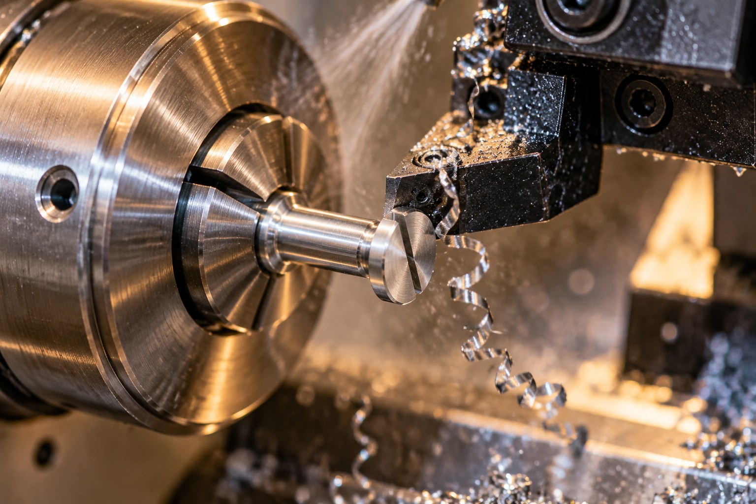
Turning the head, shoulder, collar and thread on one axis is what gives the part its concentricity; the slot is milled afterwards.
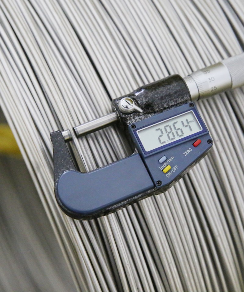
Bar stock is checked on receipt: diameter, grade and surface condition, before anything is cut.
The benefit is concentricity you can rely on: head, shoulder, collar and thread share one rotational axis because they were cut without re-chucking, which is exactly what a pivot or a locating shoulder needs. The cost is cycle time, and that is why a turned shoulder screw is quoted per drawing rather than per kilogram. Free-cutting carbon steel is the usual choice for this part because it holds a clean shoulder diameter and a crisp slot floor without tearing; where corrosion matters more than cost, the same drawing is produced in stainless and the finish section is dropped entirely.
|
Engineering Review Before Production
On a head part the trouble starts early: where the thread begins, how the head blends into the shank, and how much room the zinc plating needs. All three are settled at drawing review, before a die is ordered.
Basis: drawing or sample reviewed at quotation; the sizes that decide fit agreed in writing.
|
Manufacturing Route Matched to Your Design
The same head can be produced several ways, and the route decides how the thread behaves in assembly. This part is made by the forming and threading route recorded for this part.
Basis: the forming route recorded for this SKU, not a house default.
|
|
Inspection Focused on Critical Features
Assembly depends on the thread, the drive depth and the zinc plating — not on how the part looks. Those are gauged in the state your drawing names: GO/NO-GO on the thread, zinc plating against the approved sample, drive checked with the matching bit.
Basis: in-house thread gauges and measuring instruments; results recorded per batch.
|
From Approved Samples to Repeat Production
A first article that passes is not yet a repeatable part. The approved sample fixes the drawing revision, the material lot, the die and the measuring method for the thread, so the next order runs on the same set.
Basis: first-article approval with you before the batch runs.
|
MANUFACTURING
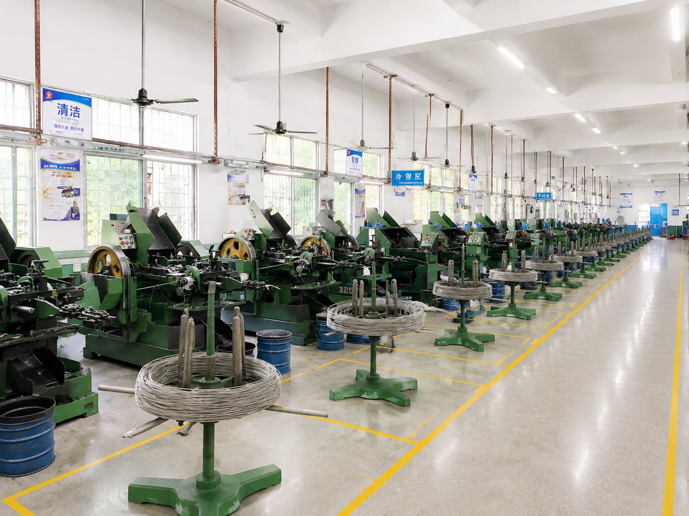
Turning, milling, plating and inspection on one floor
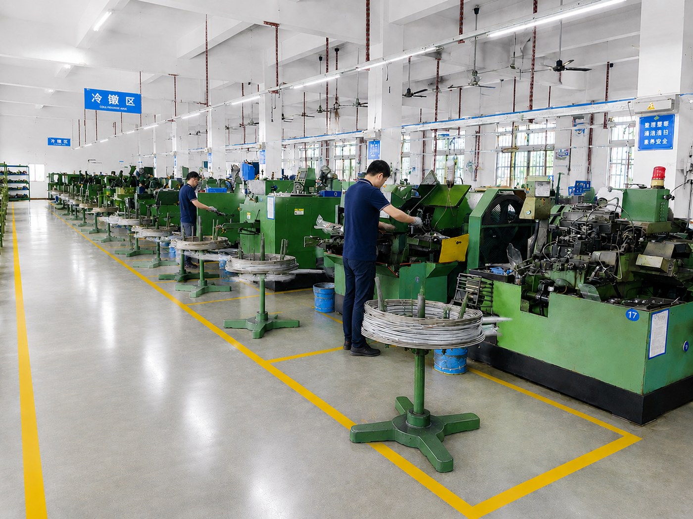
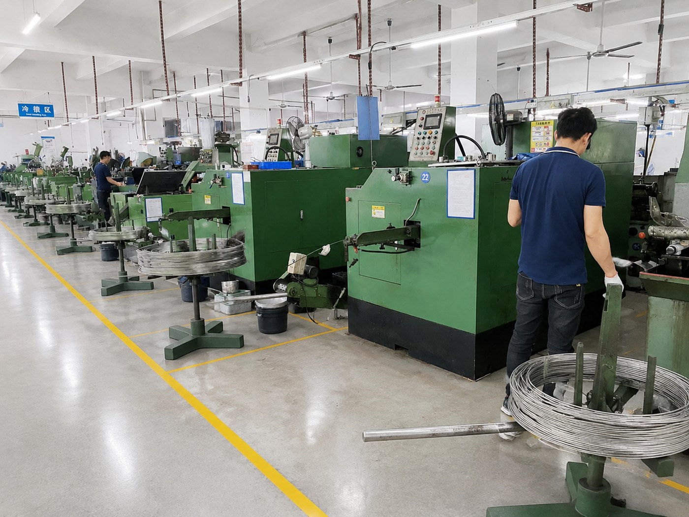
Manufacturing since 1998 in Shenzhen, Bao’an — turning, secondary machining, thread production, plating and inspection under the same roof, so a change in the slot or the plating is handled in one plant instead of across three suppliers.
|
1998
Manufacturing since
|
89
Countries and regions served
|
10+
Inspection instruments
|
8,678+
Customers served
|
 |
||
|
INSPECTION
Per batch inspection against the drawing
Shoulder diameter and length, collar face squareness, head thickness, slot width and depth on a sectioned sample, thread gauging after plating, and torque on the slot.
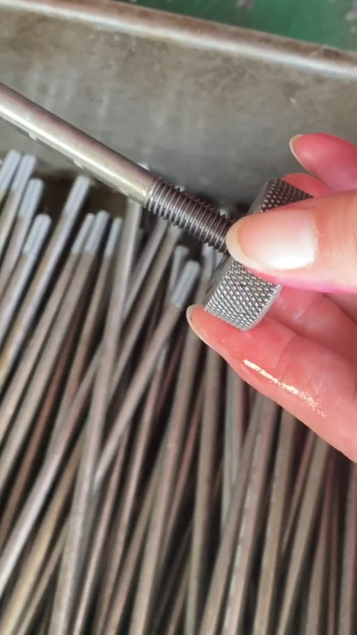 Thread gauging — GO / NO-GO after plating, not before |
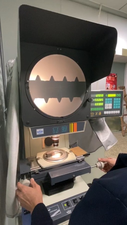 Dimensions — shoulder diameter, length and head thickness |
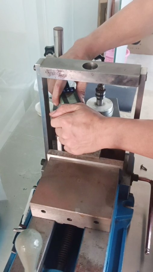 Torque — slot deformation checked on the batch sample |
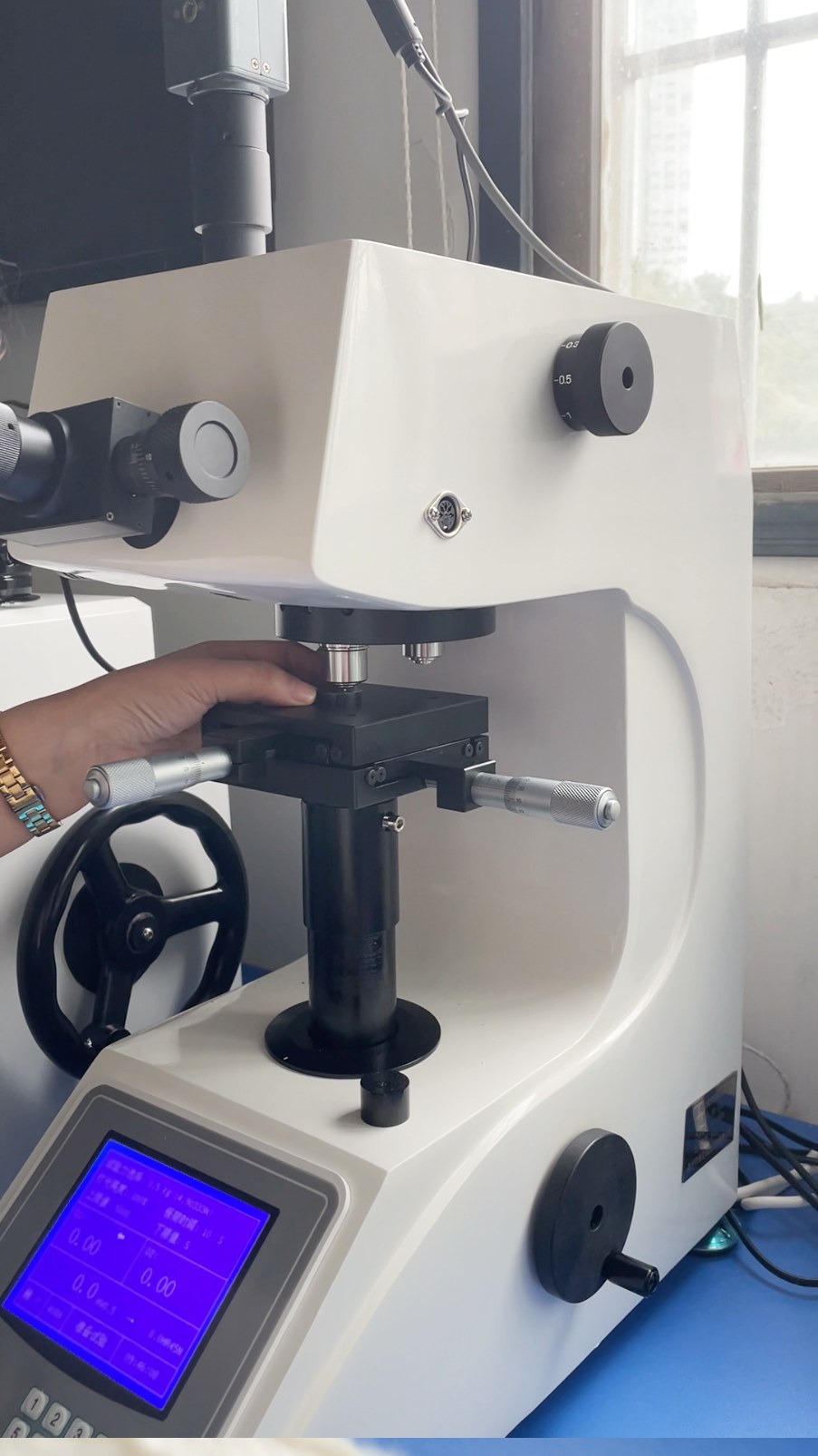 Hardness — base material checked before plating |
Inspection follows the drawing and the agreed inspection plan; records are kept per batch and stay with the lot.
CERTIFICATES
Quality system, material compliance and brand documents
ISO 9001 for the quality system, RoHS documentation for the materials we supply, and the certificates behind the Shi Shi Tong brand.
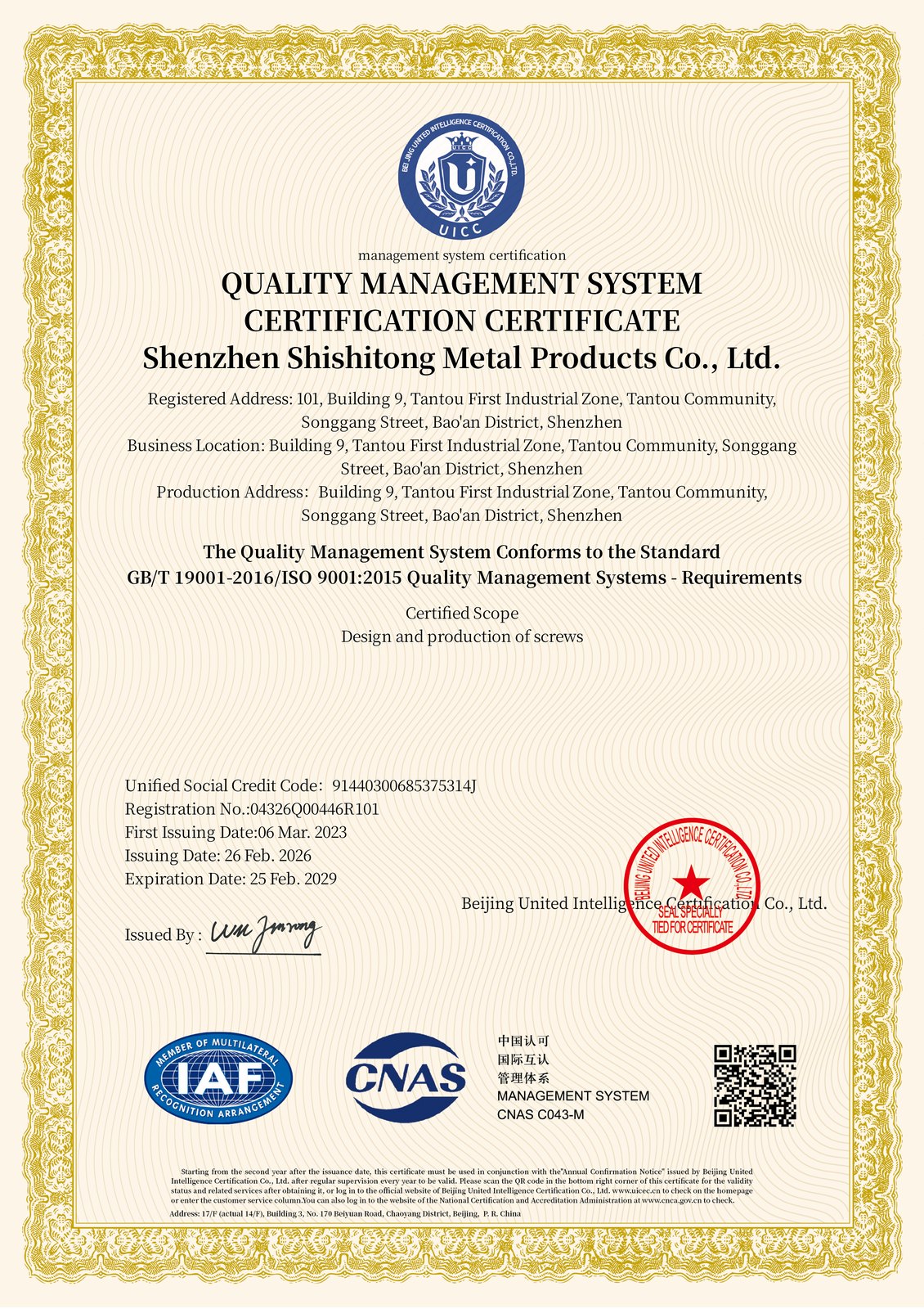 ISO 9001:2015 |
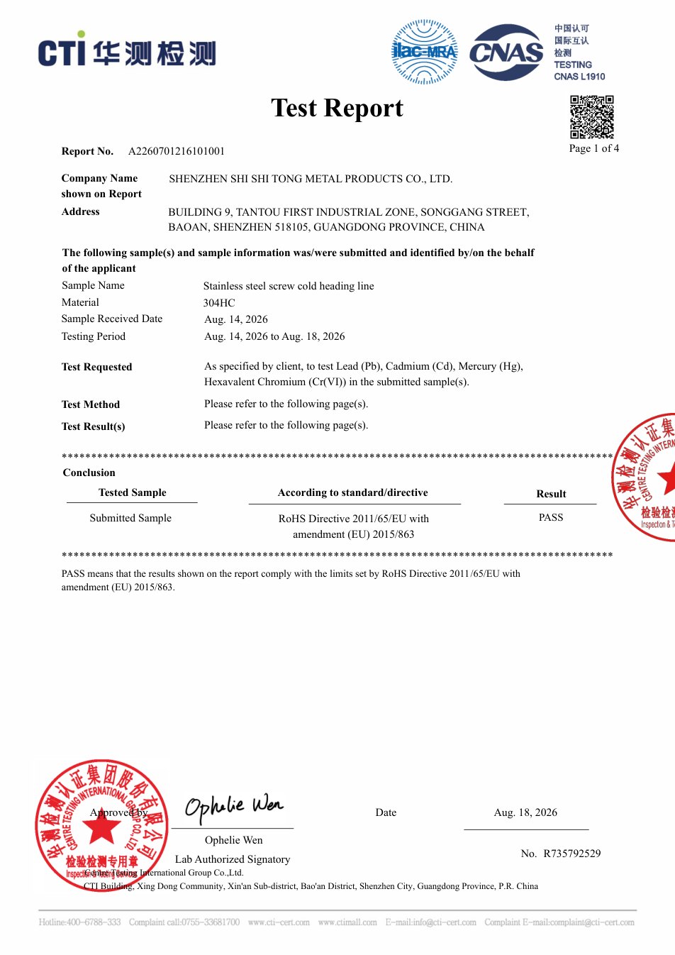 RoHS compliance |
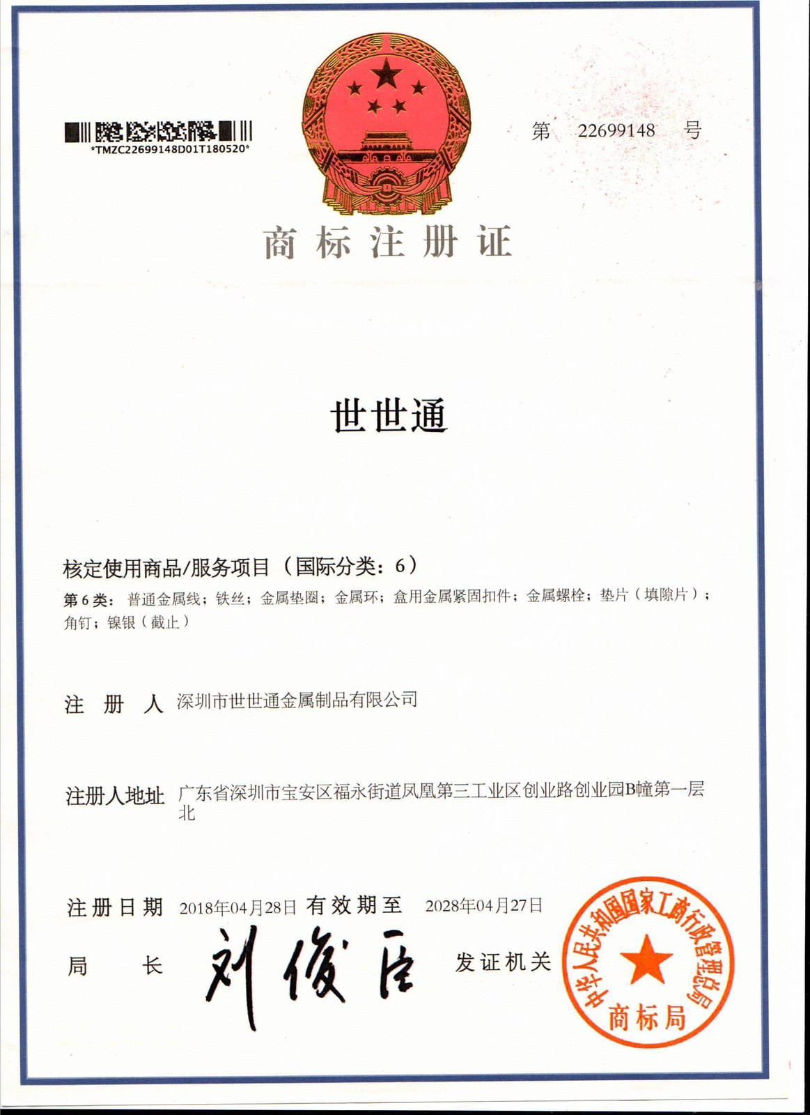 Registered trademark |
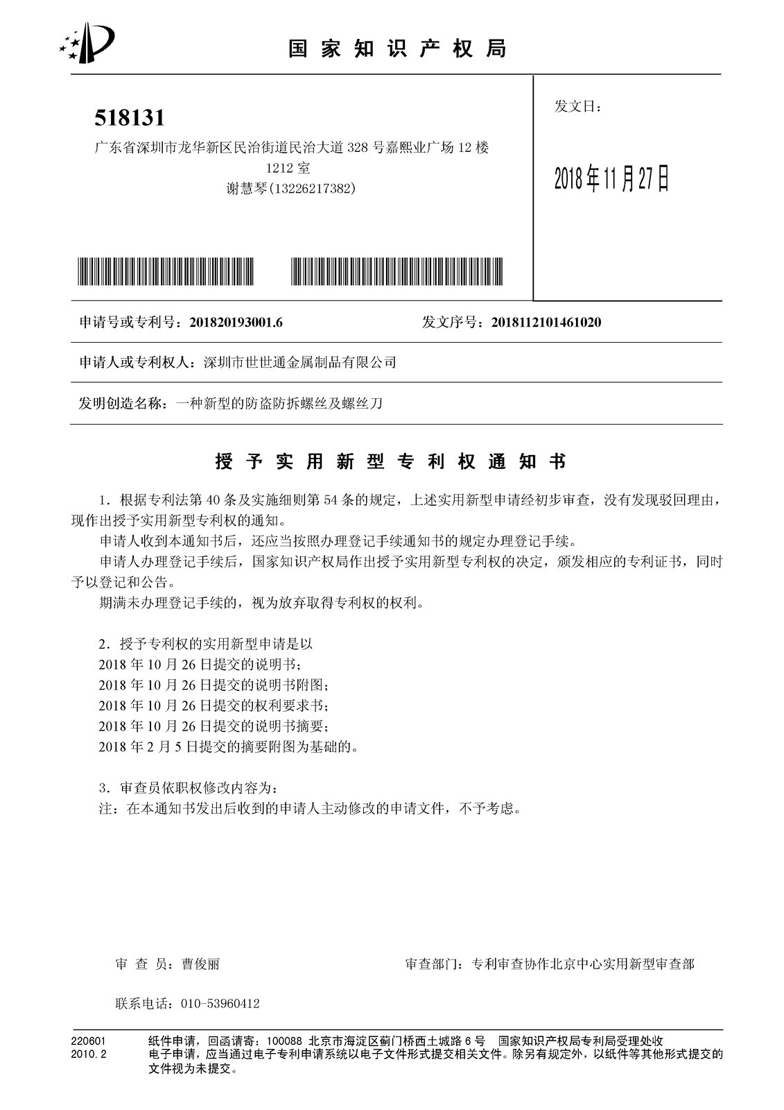 Utility model patent |
Sheet-metal enclosures and cabinet hardware

A cover, a door bracket or a guard is hinged on thin powder-coated sheet. Run an ordinary machine screw through it and the thread bears on the hole edge: every open-close cycle works the paint and the sheet, the hole opens up, and the door drops until it rubs the frame. A countersunk screw makes it worse, because the head wedges the thin material outward and cracks the coating around the hole.
The joint needs two separate functions in one part: a plain cylindrical surface to pivot on, and a flat face to carry the clamp load without crushing the sheet. It also needs a drive that a maintenance technician already has in a tool bag, because these are adjusted in the field, often on a live panel.
We control the shoulder diameter against the bracket hole so the pivot has a defined running fit; the collar diameter and face squareness so the clamp load lands on a ring, not a point; the head thickness so the head sits inside a recessed pocket without standing proud of the door face; and the slot width as a plated dimension so that a standard blade fits without bottoming or rocking. Thread length stays short so no thread runout can reach the bearing area of the bracket.
Aluminium profiles and luminaire end caps
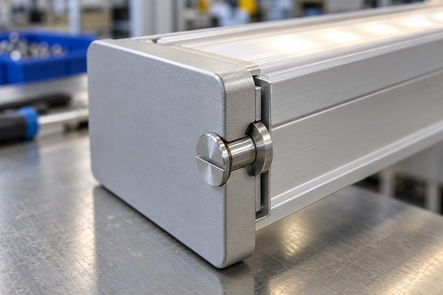
An extruded aluminium end cap is a thin wall sitting over a hollow profile. Tighten a normal screw into it and the load concentrates around the hole; the cap bows, the shadow gap at the extrusion opens on one side, and on an anodised surface the thread or a spinning washer cuts through the oxide layer and leaves a bright ring that shows on the finished fixture.
The clamp load has to be spread across the cap face, the bearing surface has to stay smooth against anodised aluminium, and the screw must not run so deep that it bottoms in the profile groove before the cap is tight.
We control the collar outside diameter and flatness so the load is distributed over the cap rather than the hole edge; the collar face finish so it does not gall the anodising; the thread length so engagement is sufficient without bottoming in the groove; and the zinc thickness on the bearing face, since a heavy local build-up is what makes a plated part sit proud on one side. The thin slotted head keeps the fixing visually flush on a fixture that is seen from below all day.
A standard machine screw is threaded up to the head and is located by its thread. This part has a plain unthreaded shoulder that provides the locating or pivoting diameter, an integral collar that provides the bearing face, and only a short thread at the end that clamps. It is turned from bar, not headed.
Because the head has to sit inside a recessed pocket or stay visually flush on a panel. The limit is the slot: a slot cut into a thin head leaves a thin web underneath it, so head thickness and slot depth are set together as one dimension chain rather than independently.
Yes, but it is a different part. The drive is cut from the same head material, so changing the drive changes head thickness, head diameter and the torque the head will take. Send the drawing and we will quote the drive you specify.
There is no catalogue figure for this, because it depends on head thickness, slot depth, slot width and the material. We establish it on samples for the batch — the slot is loaded until it deforms — and the working torque is agreed from that result, below the point where the slot mouth rounds.
Yes, and that is why slot width and thread limits are specified as plated dimensions. Plating closes the slot by roughly twice the coating thickness and builds on the thread flanks, so parts are gauged after plating. If your assembly uses a closely toleranced blade or a tight tapped hole, tell us the plated limits.
Yes. The geometry is turned either way, and the finish section is dropped for stainless. Note that stainless changes the friction behaviour in the thread and the slot — galling becomes the risk rather than corrosion — so the torque setting is reviewed with the material change.
CUSTOMERS
Buyers and engineers on the floor
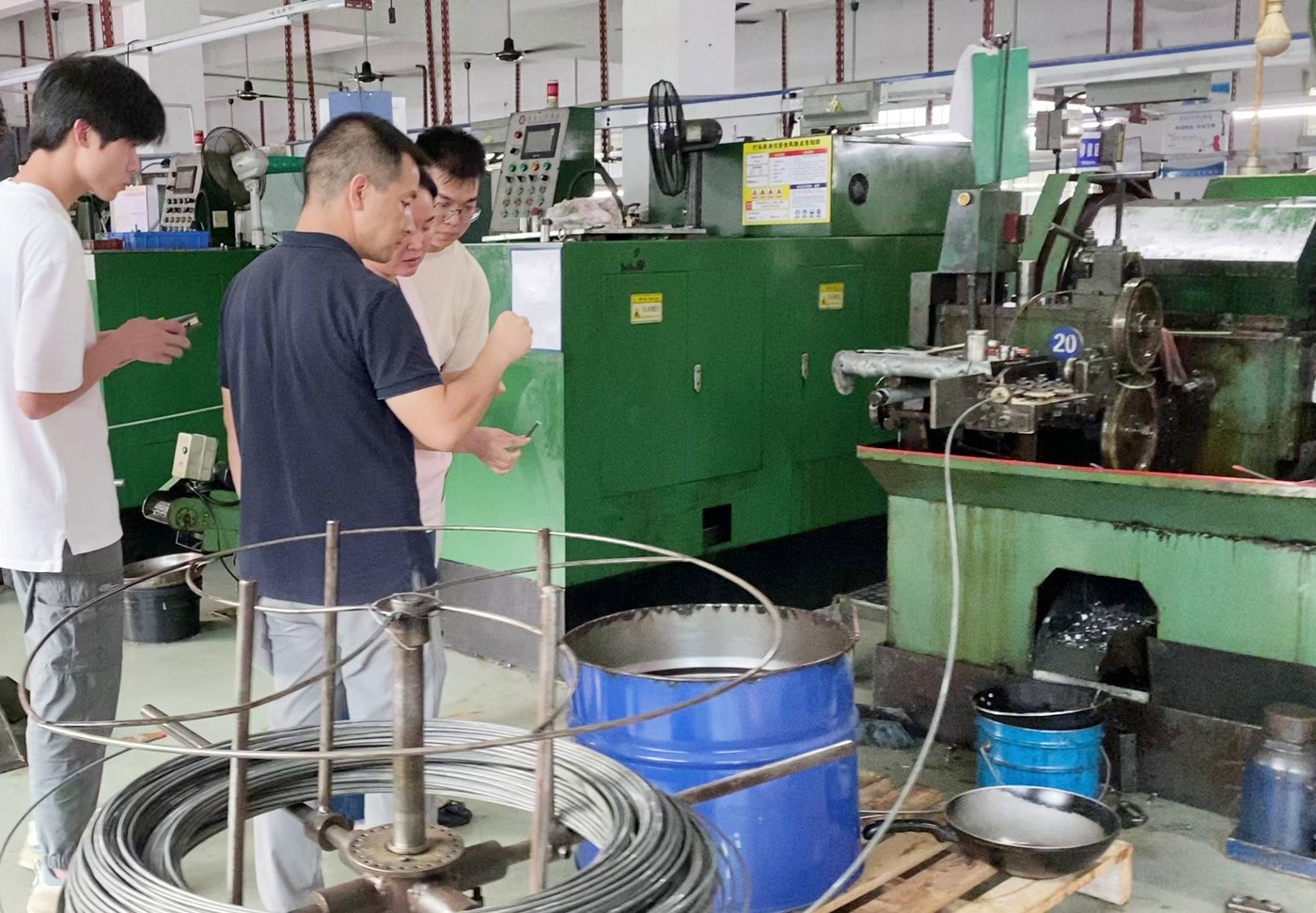
Customer visits are handled on the floor: the drawing, the sample and the inspection records are reviewed together at the bench where the parts are made.
Most of the questions on a part like this are answered faster in front of the machine than in an email thread — which set-up faces the collar, how the slot is milled, what the plated slot measures. If you are in Shenzhen, the plant is in Bao’an and a visit can be arranged around your schedule.
|
Stainless Steel Hex Screws
Turned 303 hex head with a Phillips cross in the face, plain shoulder and short thread.
|
Stainless Steel Pan Head Machine Screws
Low pan head, full machine thread, plain cleaned and passivated.
|
|
Stainless Steel Truss Head Machine Screws
Wide truss head with a combined cross and slot drive, full thread.
|
Cross Recessed Head Machine Screw
Cheese head with a cross recess, blue-white zinc on carbon steel.
|
|
316 Stainless Steel Self Tapping Screws
Pan head with a combined drive, half-length self-tapping thread.
|
To quote this part we need the drawing or the six numbers that describe it: head diameter and thickness, shoulder diameter and length, collar diameter, and thread size and length, plus material, finish and the plated tolerances that matter to your assembly. Send them through the enquiry form and we will come back with a price, a lead time and the process route we intend to run.
Related reading: screw terms and head type definitions, and certificates and compliance documents.

 +86 13143444311
 sst@szsst88.com