Tel:
+86 13143444311
Email:sst@szsst88.com
Fax:+0086-755-27322278
Address:Building 9, First Industrial Zone, Tantou Industrial City, Songgang Street, Baoan District, Shenzhen 518105, Guangdong, China
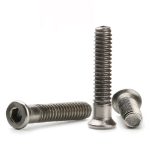
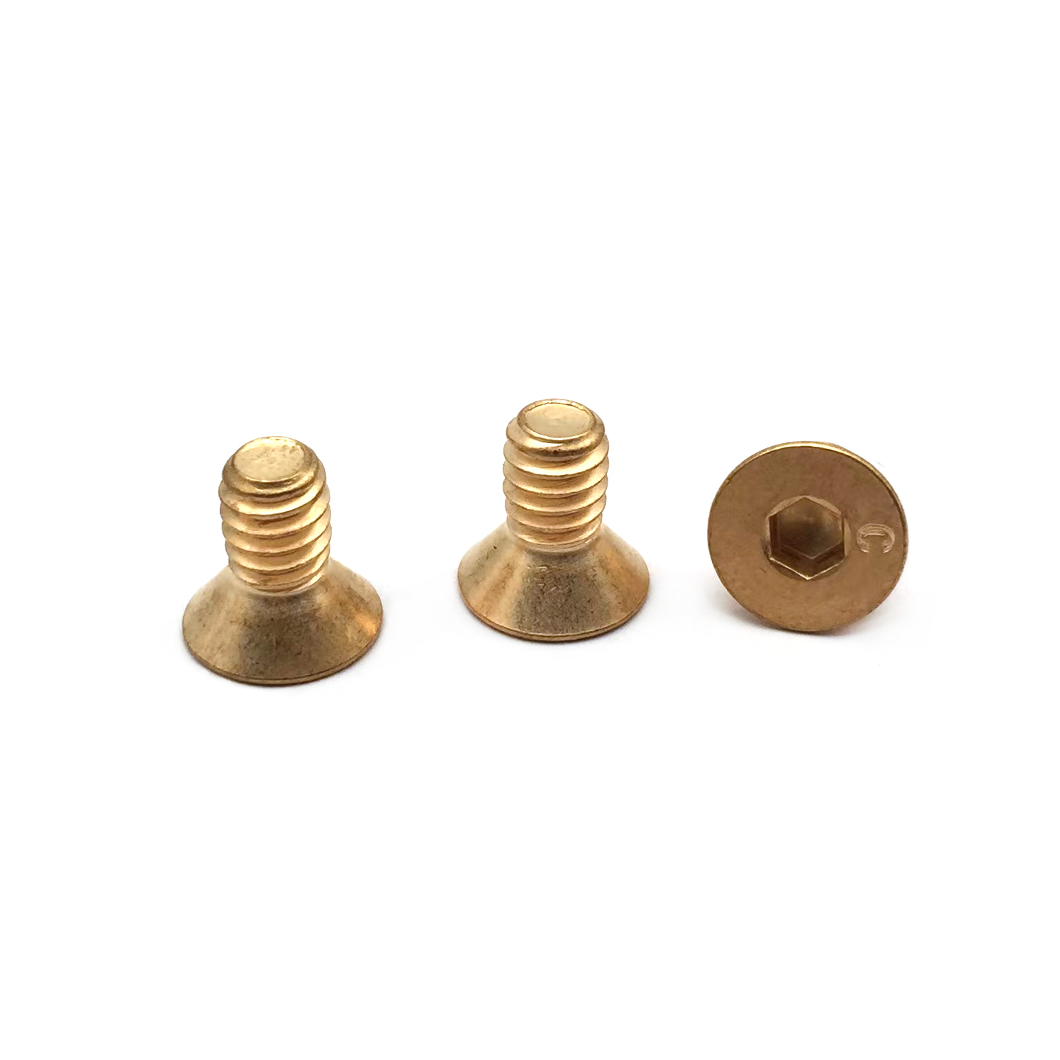
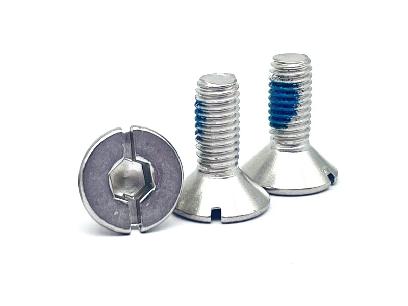
Type:Beryllium copper hex socket flat head cap screws with logo
Materials:Beryllium copper
Surface treatment:Plain
Head Type:Countersunk head
Drive type:Hex socket (Allen)
Marking:Logo on the head (per drawing)
Thread:Machine thread
Forming:Single-die cold heading
Number:1674
We manufacture hex socket flat head cap screws in beryllium copper with a countersunk head, a hex socket and a plain finish, marked with your logo on the head. Head angle, socket size and depth, logo placement, thread class and alloy temper are made to your drawing and artwork.
Watch the factory video·Email sst@szsst88.com
ISO 9001:2015 · Manufacturing since 1998 · 8,678+ customers · 89 countries and regions
Made to order – there is no stock catalogue. Each part is produced to your drawing, and production starts after drawing review and first-article approval.
A flat head cap screw is a socket-driven screw with a conical head that sits into a countersink, so the top of the head finishes level with the panel. The part on this page is made in beryllium copper, with a hex socket, a machine thread, a plain finish and your logo marked on the head.
Countersunk head. The underside is a cone, and the cone angle has to match the countersink in the panel. Match the angle and the head disappears into the surface; mismatch it and the head stands proud on one side and never looks flush however hard it is driven.
Hex socket drive. The socket is a hexagon formed into the head and driven with an Allen key. On a countersunk head the socket depth is limited by the cone, so socket size and depth are set with the head geometry rather than chosen from a table.
Beryllium copper. The alloy brings high strength, non-magnetic behaviour, good electrical and thermal conductivity, and a non-sparking surface, which is why a flat head cap screw in this material turns up in contact and instrument work rather than in general assembly.
Together these decide the fit: the head sits flush, the key engages the socket, the thread holds the joint, and the logo reads on the head without breaking either the cone or the socket.
This flat head cap screw is made from beryllium copper wire in the condition stated on the drawing. The alloy and its temper are recorded with the lot, and the material certificate follows the batch, because the strength and the conductivity of the part depend on both.
The countersunk head is formed in the die, and the hex socket is punched in the same operation. The logo is added on the head face: either struck in the die or marked in a separate step, depending on the logo and the head size. Either way the mark has to stay inside the flat of the cone and clear of the socket.
A logo on a countersunk head is a marking problem before it is a branding problem. A mark that is too deep lifts metal at the edge of the socket; one that is too shallow disappears after handling. The drawing fixes the position, the size and the depth, and the first article is checked against the customer’s artwork.
The thread is a machine thread, rolled on the same machine, and the parts are supplied plain. Plain beryllium copper darkens with handling, which is acceptable where the part is functional; where the face is visible, nickel or gold plating is specified and the thread is gauged after plating.
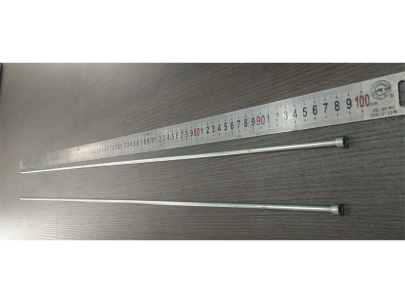
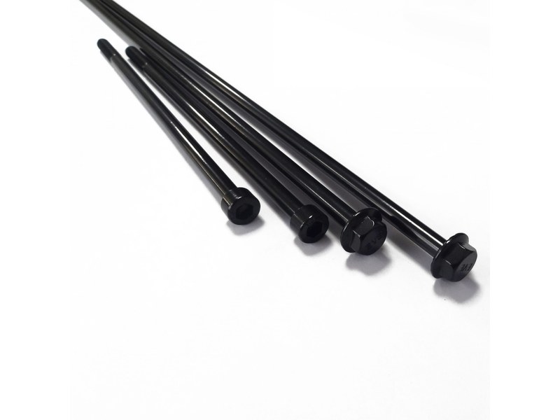
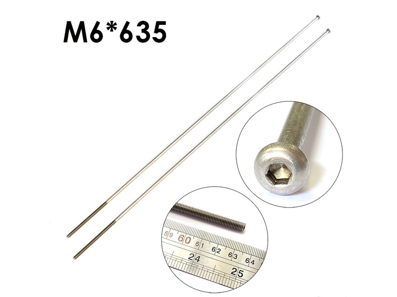
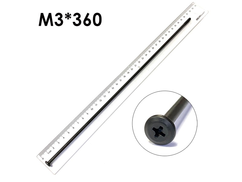
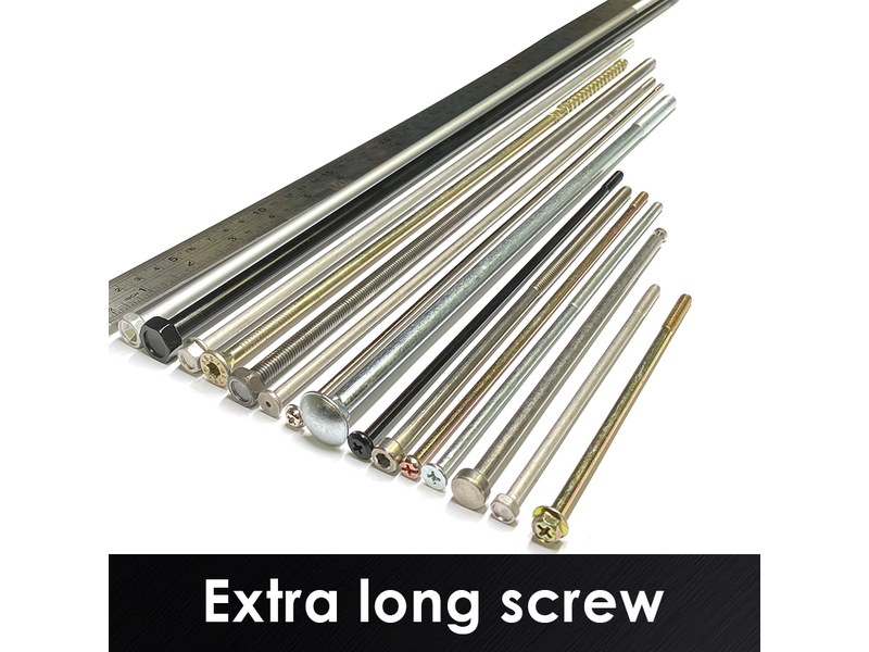
Flat head cap screws of this type are quoted from M2 to M8 and in lengths up to 100 mm, with the head angle, the socket and the logo measured on the projector and the thread gauged. Where a long version is required, custom lengths up to 2,000 mm are subject to DFM review after drawing submission.
| Item | How it is defined | What we control |
|---|---|---|
| Head diameter and angle | The cone that matches the panel countersink | Checked on the projector on the first article |
| Head height | The depth the head sinks into the countersink | Measured from the bearing cone |
| Hex socket size and depth | The Allen key and its engagement | Checked with the key and on the projector |
| Logo | Position, size and depth on the head face | Checked against the customer artwork on the first article |
| Thread size and length | Machine thread to the drawing | Gauged per batch |
| Total length | From the top of the head to the tip | Datum stated on the drawing; measured on the shop plate |
Each size is quoted against the joint it closes. On a countersunk part the cone angle, the panel thickness and the head height are reviewed together, because a head that is right for one panel stands proud in another even at the same nominal size.
Head height is measured from the bearing cone and the total length from the top of the head. The batch is checked on the features the process can drift on: head angle, socket depth and thread class.
The hex socket is the drive of a flat head cap screw, and on a countersunk head it sits in a cone that is already thin at the rim. The socket has to be deep enough for the key to engage without rocking, and shallow enough that the head does not open through the cone when the screw is driven to torque.
Key fit is checked with the Allen key that will be used on the line. On a small socket a key that is a few hundredths wide rocks, and the corners round at the bottom where the engagement is shortest. The damage is not visible until the screw is loosened and re-driven, which is why the first article is checked with the key and not only on the projector.
The socket also competes with the logo for space on the head face. A large logo pushed towards the socket thins the wall between them, and that wall is what carries the torque. Position, size and depth are reviewed together before the die is cut.
| Socket item | Why it matters on a countersunk head | What we control |
|---|---|---|
| Across flats | It is the key size | Checked with the key and on the projector |
| Socket depth | Engagement and head strength | Checked on the projector |
| Socket form | Corners that take the torque | Formed with the punch and checked on the sample |
| Socket-to-logo wall | Material between the socket and the mark | Reviewed on the drawing and checked on the first article |
This flat head cap screw is supplied in plain beryllium copper. There is no coating to build on the thread, the socket or the logo, so the dimensions the die produced are the dimensions that assemble, and the conductivity of the contact faces is not interrupted by a plated layer.
| Finish | How it protects | Effect on head and thread | Typical use |
|---|---|---|---|
| Plain beryllium copper | Alloy resists corrosion without a coating | No build-up; dimensions as formed | Contacts and non-magnetic assemblies |
| Nickel plated | Barrier layer over the copper alloy | Build-up on thread; gauged after plating | Visible parts and solder-resistant faces |
| Gold plated | Thin noble layer over nickel | Build-up on thread; gauged after | Low-resistance contacts |
| Tin plated | Solderable barrier layer | Build-up on thread; checked after | Solder and busbar joints |
| Silver plated | High-conductivity noble layer | Build-up on thread; gauged after | High-current contacts |
Salt-spray exposure is agreed per project and written on the drawing. Plain beryllium copper darkens in damp air without losing function, so the acceptance criterion for a plain part is corrosion of the thread and the contact face, not a colour change on the head.
Packing protects the cone, the socket and the logo. Screws are packed in layers so the heads do not rub, and the label carries the batch, the alloy lot and the finish reference.
Three assemblies where a beryllium copper flat head cap screw is chosen for the material rather than the head shape, and what the screw has to do instead:
| Where it sits | The screw clamps a contact or a busbar where the joint has to carry current and the head sits in a countersink. |
| When it goes wrong | A plated or tarnished contact face raises resistance, and a magnetic screw distorts the field around a sensor. |
| Why it happens | The joint carries current, the parts are small, and the assembly is checked for resistance after build. |
| What we control | Alloy and temper recorded, plain contact faces kept free of coating, and the thread gauged per batch. |
| Where it sits | The screw holds a cover or a fitting on equipment used where a spark is not acceptable. |
| When it goes wrong | A steel screw that sparks on contact defeats the purpose of the enclosure, and a proud head catches a tool. |
| Why it happens | The environment is classified, the parts are non-sparking by material, and the joint is opened for inspection. |
| What we control | Beryllium copper grade on the drawing, head flush in the countersink, and the material certificate with the batch. |
| Where it sits | The screw fixes a sensor housing or a mount where a magnetic fastener would disturb the reading. |
| When it goes wrong | A magnetic screw close to a sensor shifts the measurement, and a corroded thread seizes in a salt atmosphere. |
| Why it happens | The instrument is sensitive, the environment is wet, and the parts are non-magnetic by requirement. |
| What we control | Non-magnetic alloy on the drawing, thread gauged, and salt-spray exposure agreed per project. |
Four reasons that matter on a flat head cap screw in beryllium copper with a logo, each tied to what the drawing has to prove:
|
Head, socket and logo reviewed together
The cone angle, the socket depth and the logo position are reviewed before the die is cut, so a mark that would thin the socket wall is raised with you first. Basis: Head, socket and logo reviewed before tooling. |
Formed, threaded and marked in one route
The head, socket and thread are produced in one heading route, and the logo is applied in the agreed step, so the mark stays centred on the head axis. Basis: One route for head, socket, thread and logo. |
|
Socket key-checked and logo checked to artwork
The socket is checked with the Allen key and the logo against your artwork on the projector, so the part that passes is the part that drives and reads. Basis: Socket fit and logo checked on the first article. |
First article to repeat production
The first article fixes the drawing revision, alloy lot, die set and logo tooling; repeat orders are compared against that record. Basis: First article and logo artwork signed off before the batch. |
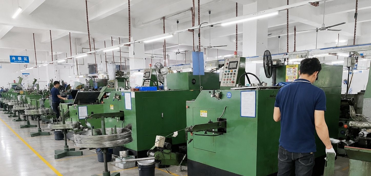
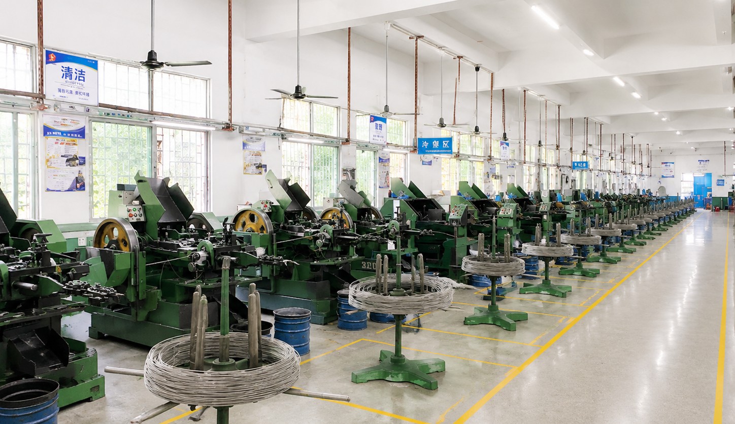
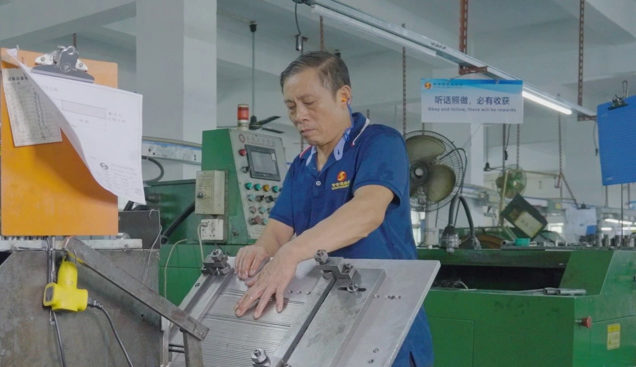
Shi Shi Tong forms these flat head cap screws on a single-die header: the countersunk head and the hex socket are struck in the die, the logo is applied in the agreed step, the thread is rolled, and the parts are supplied plain or plated as the drawing states. The first part of every run is measured on the head, checked with the key and compared with the logo artwork before the batch continues.
|
|
Between runs the die insert is changed to the drawing head and the socket punch to the key size; the logo tooling is set with the die, and the first part is checked against the artwork. The setting is recorded, and plated parts are checked again after the bath so the record covers both conditions.
What decides whether a flat head cap screw passes is not the colour of the alloy: it is the head angle and height, the socket size and depth, the logo position and depth, and the thread class. The inspection agreement covers those, and the criteria come from the drawing and your artwork.
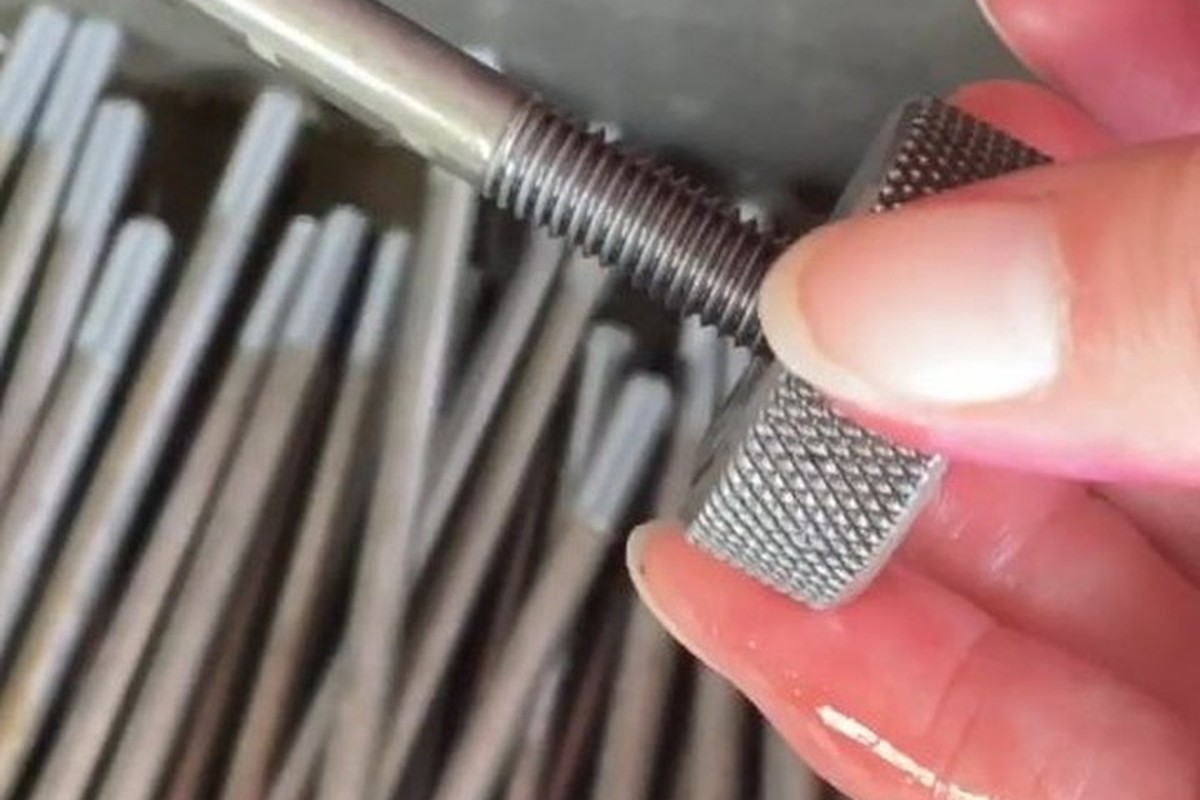
Thread gauging against GO/NO-GO gauges |
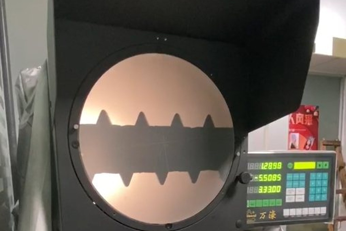
Head, socket and logo on the projector |
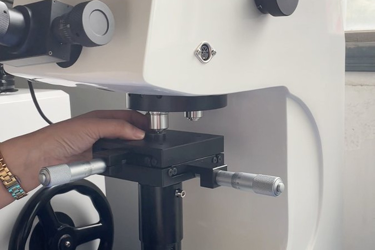
Hardness testing where the drawing requires it |
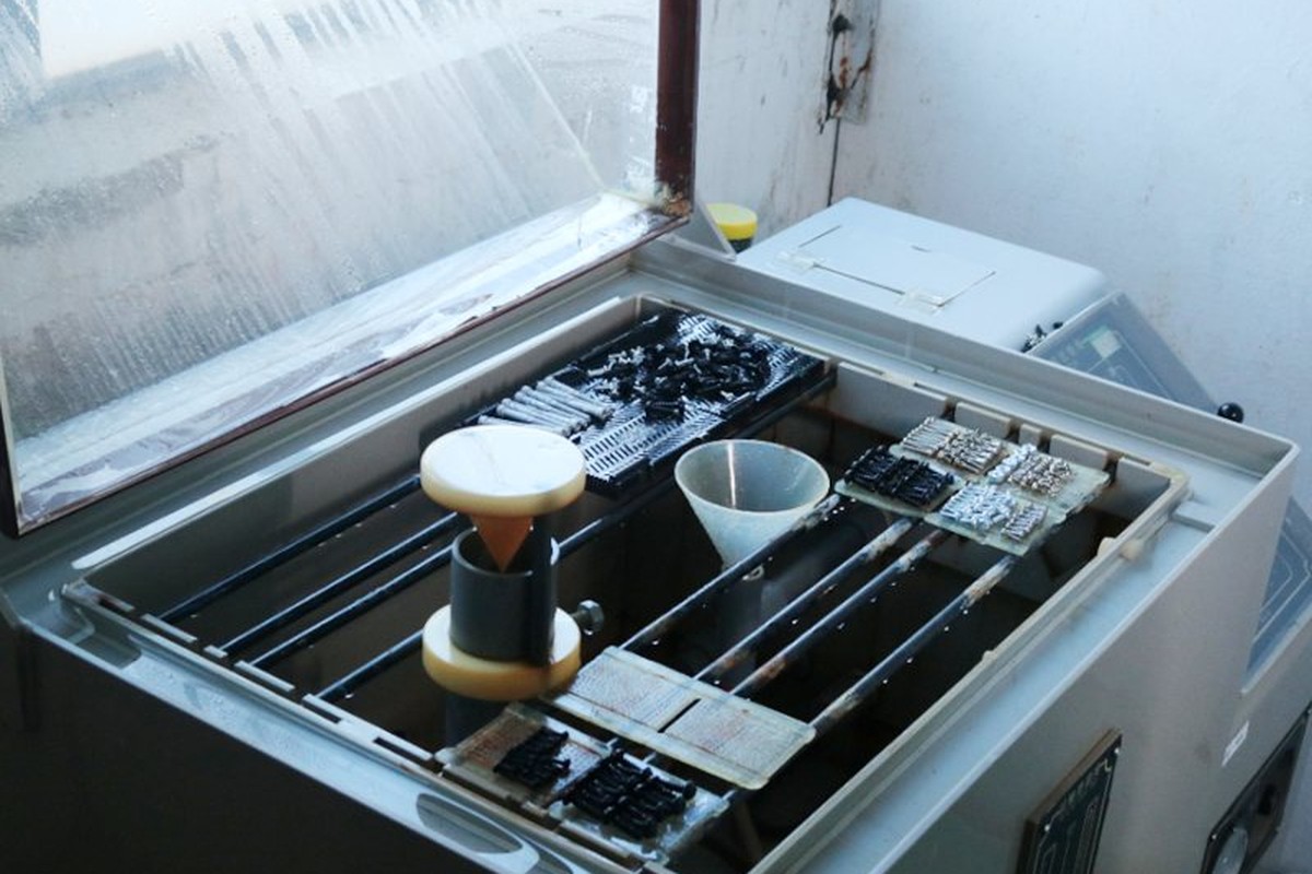
Salt-spray testing of the agreed finish |
Each batch is recorded against the drawing revision: head and socket from the first article, the logo compared with the artwork, and the thread gauged per batch. If a gauge or the logo check fails, the parts back to the last good setting are held and re-checked.
Where a third-party report is required for the alloy or the finish, it is listed on the drawing so the paperwork ships with the parts, and the batch number on the label matches the record used for inspection.
Every flat head cap screw shipment is traceable to the beryllium copper it was made from. The alloy, temper, lot number and standard are recorded on the material certificate supplied with the parts, and the inspection records follow the criteria agreed on the drawing.
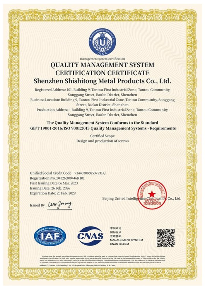
ISO 9001:2015 |
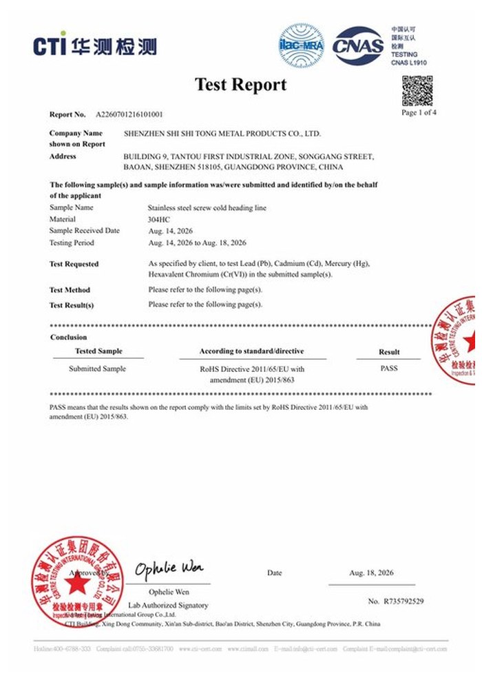
RoHS test report |
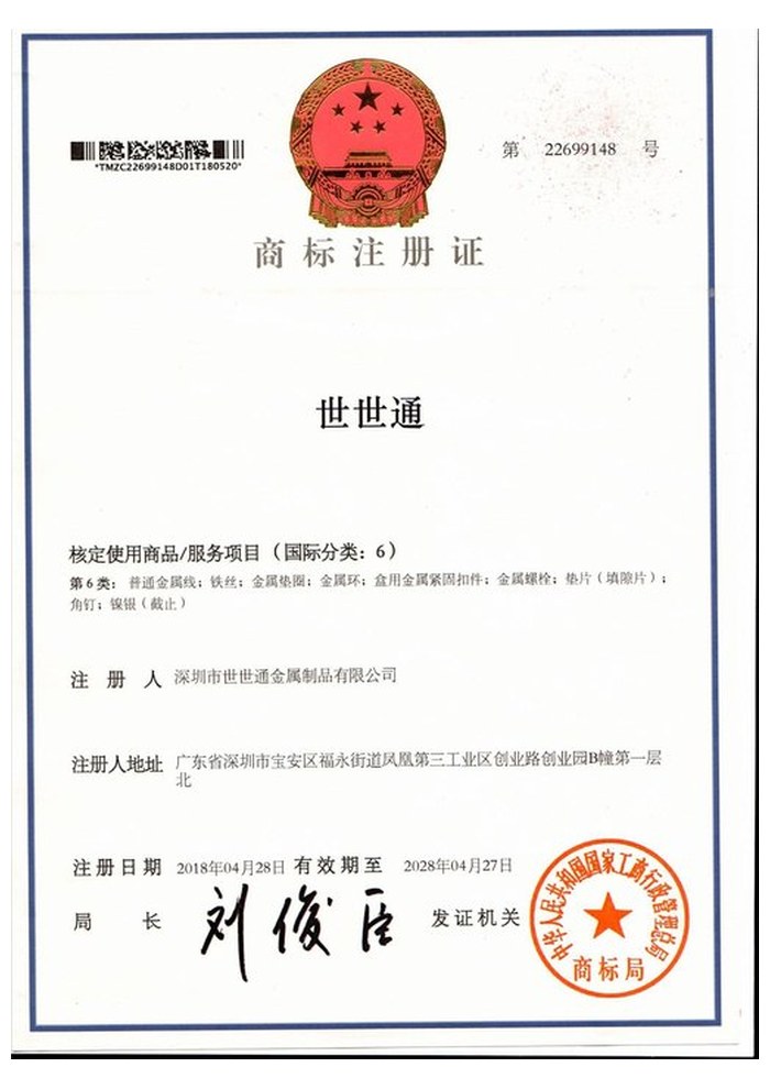
Registered trademark |
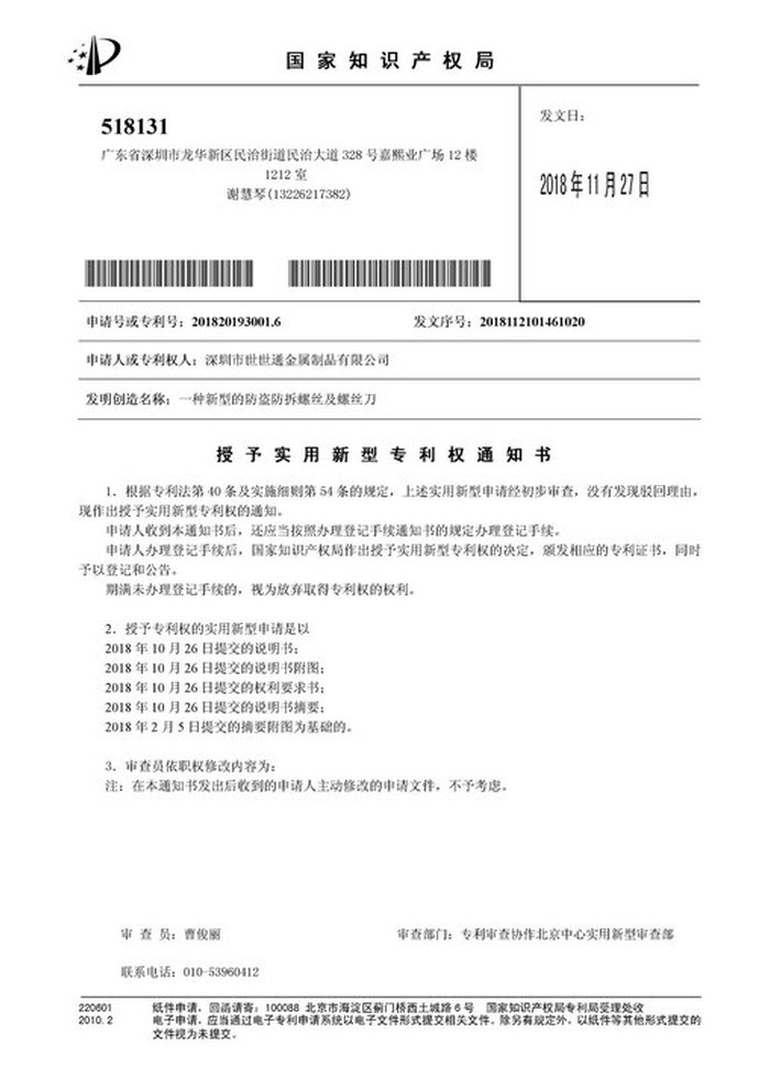
Patent: security screw and driver |
With each batch we supply the material certificate, the inspection record for the criteria on the drawing and, where it is listed, the third-party report for the alloy or the finish. The documents carry the drawing revision and the batch number, so the paperwork can be matched to the parts.
More than 8,678 customers in 89 countries and regions have ordered from Shi Shi Tong; 87% of orders come from repeat customers and 56% through referrals. Most projects follow the same route: drawing review, first-article approval, then batches checked against that sample. Marked parts are approved against your artwork, so the logo position, size and depth are signed off before the tool is cut. Buyers visit during the process to review samples and to see how the heads and sockets are formed.
|
8,678+
customers served
|
87%
of orders from repeat customers
|
56%
of orders through referrals
|
89
countries and regions shipped to
|
Buyers and quality engineers visit for sample review, process discussion and supplier audits; the visit is arranged around production so the header and the plating line can be seen on the day the parts run.

Customer group visit – sample review |

Customer group visit – process discussion |

Customer group visit – factory tour |

Customer visit – project kick-off |

Danish customer – drawing review |
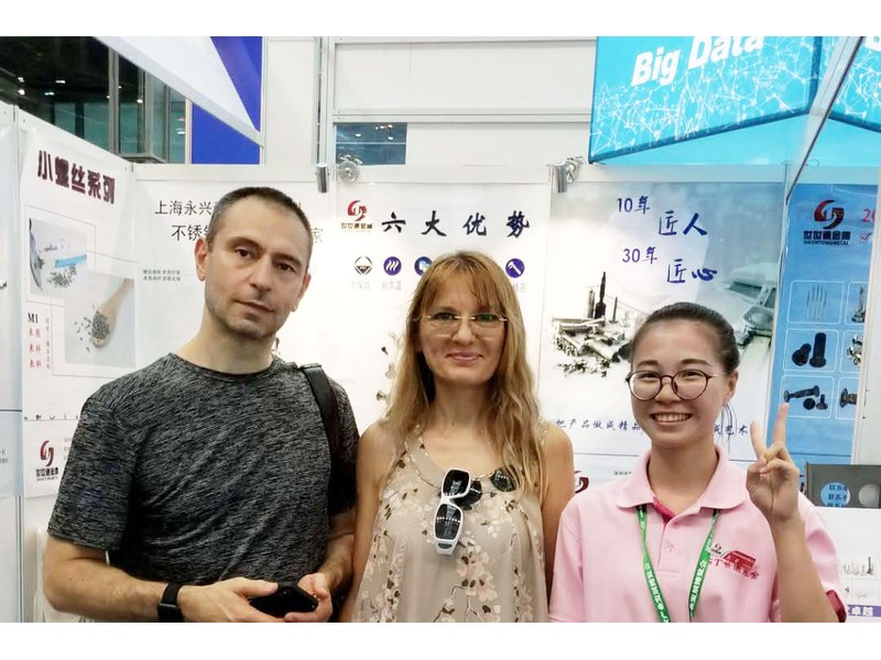
Industry exhibition – meeting customers |
It is a socket-driven screw with a conical head that pulls into a countersink until the top sits level with the panel. This one is beryllium copper with a hex socket and a logo on the head.
The alloy gives high strength, non-magnetic behaviour, good electrical and thermal conductivity and a non-sparking surface. It is chosen for contacts, non-magnetic instruments and equipment used where a spark is not acceptable.
Yes. The logo is struck in the die or marked in a separate step, and its position, size and depth are fixed on the drawing and approved against your artwork. The mark has to clear the socket and the cone.
Flat head cap screws of this type are quoted from M2 to M8 and in lengths up to 100 mm. Where a long version is required, custom lengths up to 2,000 mm are subject to DFM review after drawing submission.
It can, if it is too deep or too close to the socket. The material between the socket and the mark carries the driving torque, so the layout is reviewed before the tool is cut and checked on the first article.
Head diameter, height and countersink angle, hex socket size and depth, logo artwork and placement, thread size and length, total length and datum, alloy and temper, finish and quantity.
How a flat head cap screw project runs from drawing to repeat delivery:
|
1
Send the drawing and artwork
|
→ |
2
Head, socket and logo review
|
→ |
3
First article approval
|
→ |
4
Batch production and repeat orders
|
Each step is confirmed with you before the next one starts; the drawing revision and the approved logo from the first article are what repeat orders are checked against.
For a flat head cap screw quotation, send the drawing with the head diameter, height and countersink angle, hex socket size and depth, thread size and length, total length and datum, alloy and temper, finish, and the logo file with its placement.
|
Head diameter and angle
|
Socket size and depth
|
Logo file and placement
|
|
Thread size and length
|
Alloy and temper
|
Finish and quantity
|
Sending a drawing? The form below does not take attachments. Email the PDF, DXF or STEP file to sst@szsst88.com with the part name and quantity in the subject line – the drawing is reviewed and a quotation follows.

 +86 13143444311
 sst@szsst88.com