Tel:
+86 13143444311
Email:sst@szsst88.com
Fax:+0086-755-27322278
Address:Building 9, First Industrial Zone, Tantou Industrial City, Songgang Street, Baoan District, Shenzhen 518105, Guangdong, China
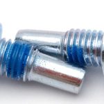
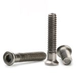
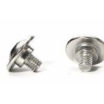
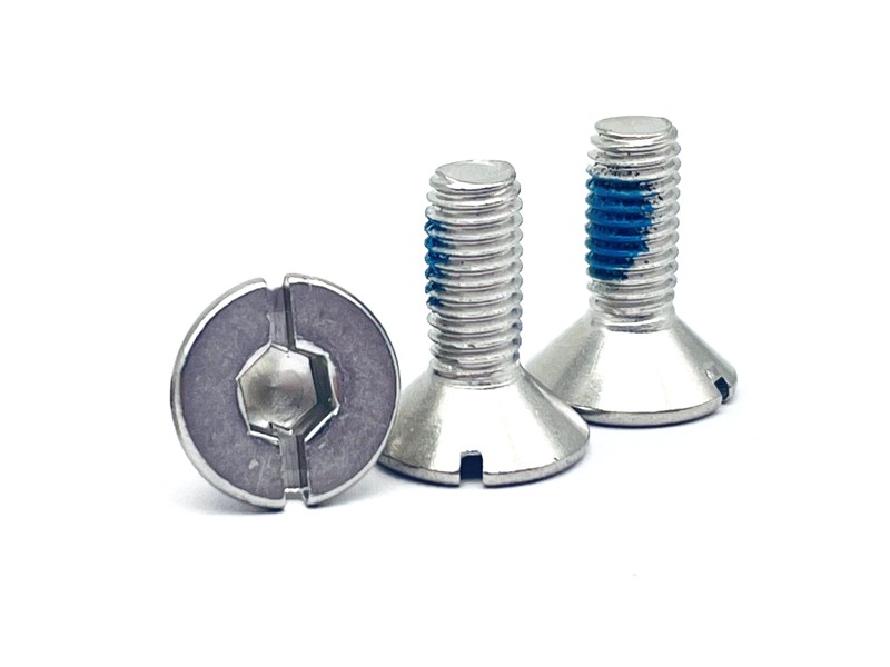
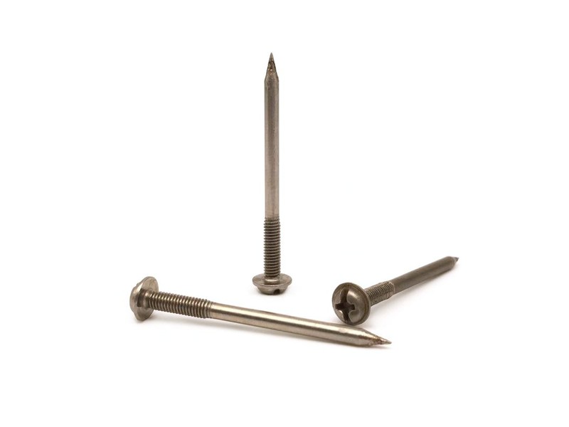
Type:Stainless cap head slotted captive head screw (turned)
Materials:Stainless steel
Surface treatment:Passivation
Head Type:Cap head
Drive type:Slotted
Thread:Partial (half) machine thread
Forming:CNC turning (bar stock)
Number:1815
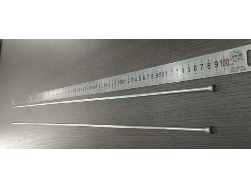
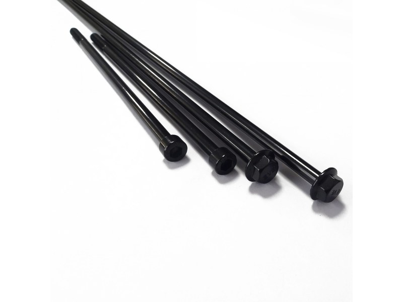
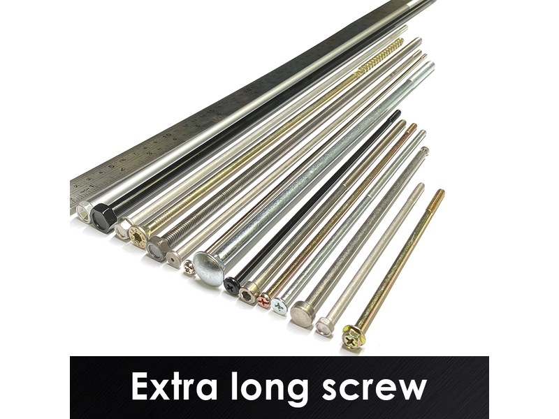
We manufacture stainless cap head slotted captive head screws turned from bar, with a neck under the head that lets a retaining clip or panel slot keep the screw with the cover, from M1.4 to M12 and up to 2,000 mm, with a partial machine thread and a passivated finish. Head, neck, slot and thread start are made to your drawing.
Watch the factory video·Email sst@szsst88.com
ISO 9001:2015 · Manufacturing since 1998 · 8,678+ customers · 89 countries and regions
Made to order – there is no stock catalogue. Each part is produced to your drawing, and production starts after drawing review and first-article approval.
A captive head screw is a machine screw designed so it stays with the cover it fastens after it has been unscrewed. The cap head carries the drive, the neck under the head gives a retaining clip or the panel slot something to hold, and the plain shank slides in the panel bore while the thread engages at the far end.
The neck is the captive feature. The head is turned at full diameter, then the neck is cut smaller and shorter than the panel bore. A retaining clip seated in that neck, or a slotted panel hole, lets the screw pull back and turn freely without leaving the cover, so a technician never has to catch a falling screw.
Cap head and slotted drive. A cylindrical cap head gives a tall, flat-topped driving face, and the single slot lets the screw be turned with a flat driver that fits in a service kit. On a captive head screw the slot is cut across the full diameter of the head, so the driver does not need to find a recess on a screw that has already been backed out.
Partial thread on a long shank. The unthreaded span is what slides in the panel and the cover; the thread engages only in the tapped body behind it. That keeps the thread out of the sliding joint and lets the screw travel in and out without cutting the panel bore.
Together these decide what the part does on site: the cover comes off with the screws still sitting in it, the screws go back into their own holes, and no loose hardware ends up inside the machine.
This captive head screw is turned, not headed. A stainless bar is cut to length and machined on a CNC lathe: the cap head, the neck, the plain shank, the chamfer and the thread run-out are cut in one setup sequence, so the neck and the head stay concentric with the shank that slides in the panel.
The neck is the dimension that matters most on a turned captive screw. Cut it too large and the retaining clip will not snap over it; cut it too small and the screw rattles in the cover or slips past the clip. Because the neck is turned in the same setup as the head and shank, its diameter is read from the same datum instead of being produced in a second operation and stacked on a tolerance.
Thread is produced after the body is turned. For stainless parts the thread is rolled where the drawing allows it, which leaves an uninterrupted grain flow at the root; where the thread has to run out into a turned relief, the relief is cut first so the rolls have somewhere to finish. The part is then deburred and passivated before the final gauge.
Captive head screws are quoted from M1.4 to M12 and up to 2,000 mm, with length usually held to +0/-2 mm on the drawing. Custom lengths up to 2,000 mm are subject to DFM review after drawing submission.
| Item | How it is defined | What we control |
|---|---|---|
| Total length | From the top face of the cap head to the tip | Datum stated on the drawing; length measured on the shop plate |
| Head diameter and height | The cap head that carries the drive and stops at the panel | Head diameter and height held to the panel counterbore |
| Neck diameter and length | The undercut that a retaining clip or panel slot holds | Neck turned in the same setup as the head and shank |
| Thread length and position | Where the thread starts and how far it runs | Thread start taken from the drawing, not from a sample |
| Slot width and depth | The flat-driver recess across the head | Slot width and depth held to the driver that will be used |
Each diameter and length combination is checked against the drawing before a quotation is issued. The neck is checked together with the head, because a clip that fits one screw may not fit the next if the neck has been turned on a different setting.
On a captive head screw, length is measured from the top face of the head, since that face is what the counterbore or the clip sits against. Head diameter, neck diameter, neck length and slot width are gauged on the first article before a batch is released, because those four dimensions decide whether the screw stays captive and whether the driver can turn it.
For a captive head screw the drawing fixes six things: thread size and pitch, thread length and position, plain shank length, total length and its datum, head and neck dimensions, and right- or left-hand direction. A seventh line matters when a clip is involved: the neck diameter and the radius the clip has to ride over.
| Parameter | Why it matters on a captive screw | What we control |
|---|---|---|
| Thread start position | It sets how far the screw can travel back before the thread disengages the body | Start dimension checked on the first article and per batch |
| Engaging length | Too short leaves the joint weak; too long runs the thread into the panel bore | Thread length and position taken from the drawing |
| Neck diameter | The retaining clip has to snap over it and hold | Neck turned in the same setup, checked on the first article |
| Slot width | A slot that is too narrow will not take the driver; too wide strips | Slot cut to the driver width and checked with it |
A stainless captive head screw is supplied with the metal as the finish, passivated so the surface is clean and the passive film is restored after machining. There is no plated layer filling the slot or building up the neck, so the clip still snaps over the diameter that was turned and the driver still fits the slot that was cut.
| Finish | How it protects | Effect on slot and neck | Typical use |
|---|---|---|---|
| Passivated stainless | Machining residue removed, passive film restored | No dimensional change; slot and neck stay as turned | Stainless captive screws, indoor and damp service |
| Electropolished stainless | Surface levelled and enriched in chromium | Edges smoothed; neck checked after polishing | Laboratory, hygienic and instrument equipment |
| Passivated plus light oil | Passive film plus a temporary barrier for transit | No dimensional change; oil cleaned before assembly | Parts stored before use |
| Zinc electroplated (carbon steel) | Sacrificial zinc layer | Build-up on the thread and neck; masked where the clip fits | Carbon steel parts in dry indoor service |
| Dacromet flake (carbon steel) | Zinc-aluminium flake layer | Thin, even film; neck checked over the coating | Wet or outdoor carbon steel assemblies |
Plain stainless parts are checked for finish and cleanliness rather than salt spray; salt-spray exposure is agreed only where the drawing specifies a coating. After passivation the part is rinsed and dried, and the slot is checked again for residue before packing, because a driver seated on a dry residue can strip the slot on the first turn.
Packing keeps the head and the neck protected. Screws are packed in layers so the neck does not rub against the carton and the slot is not nicked, and the label carries the batch and material heat so the clip fit recorded at gauge can be matched to the parts that arrive.
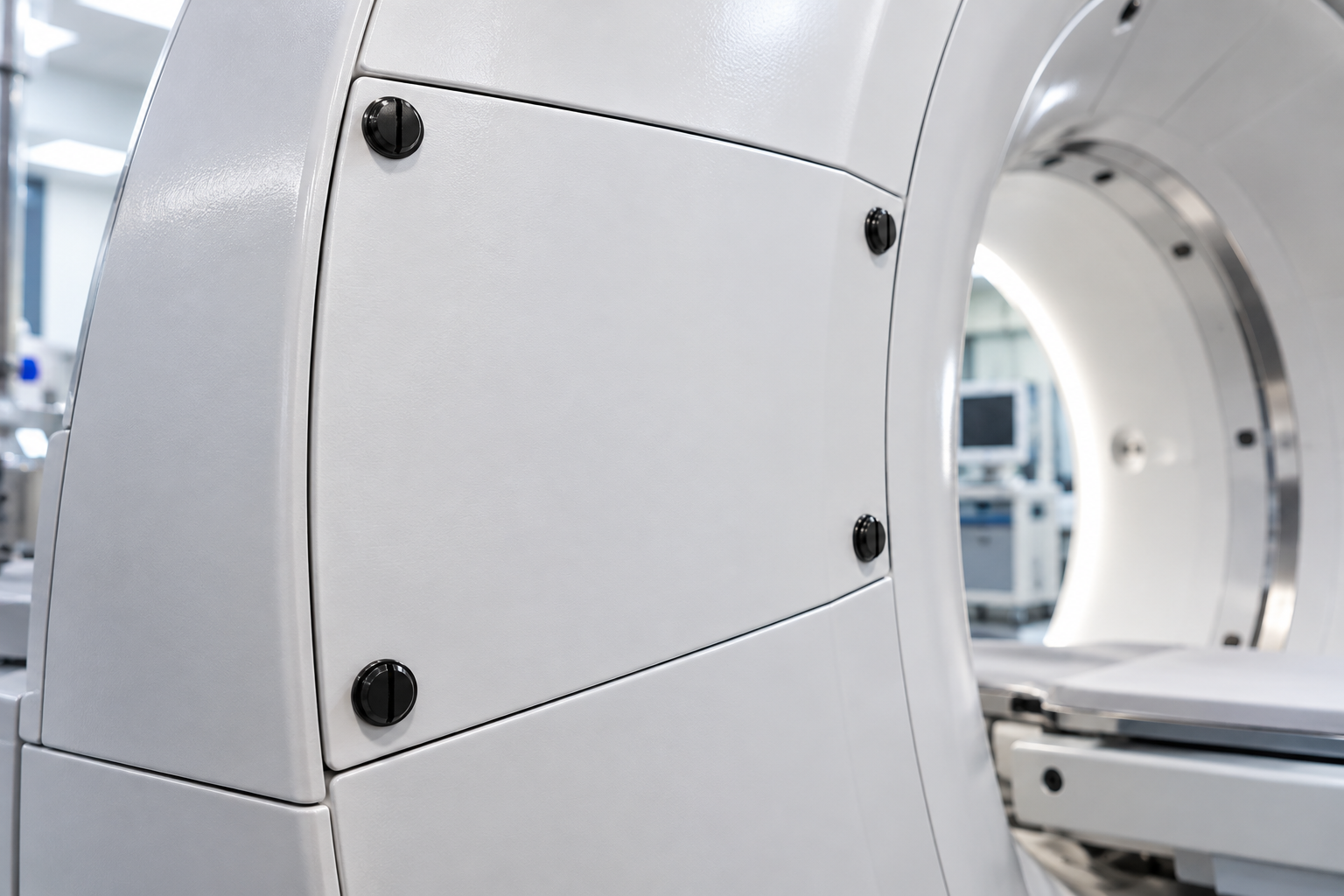
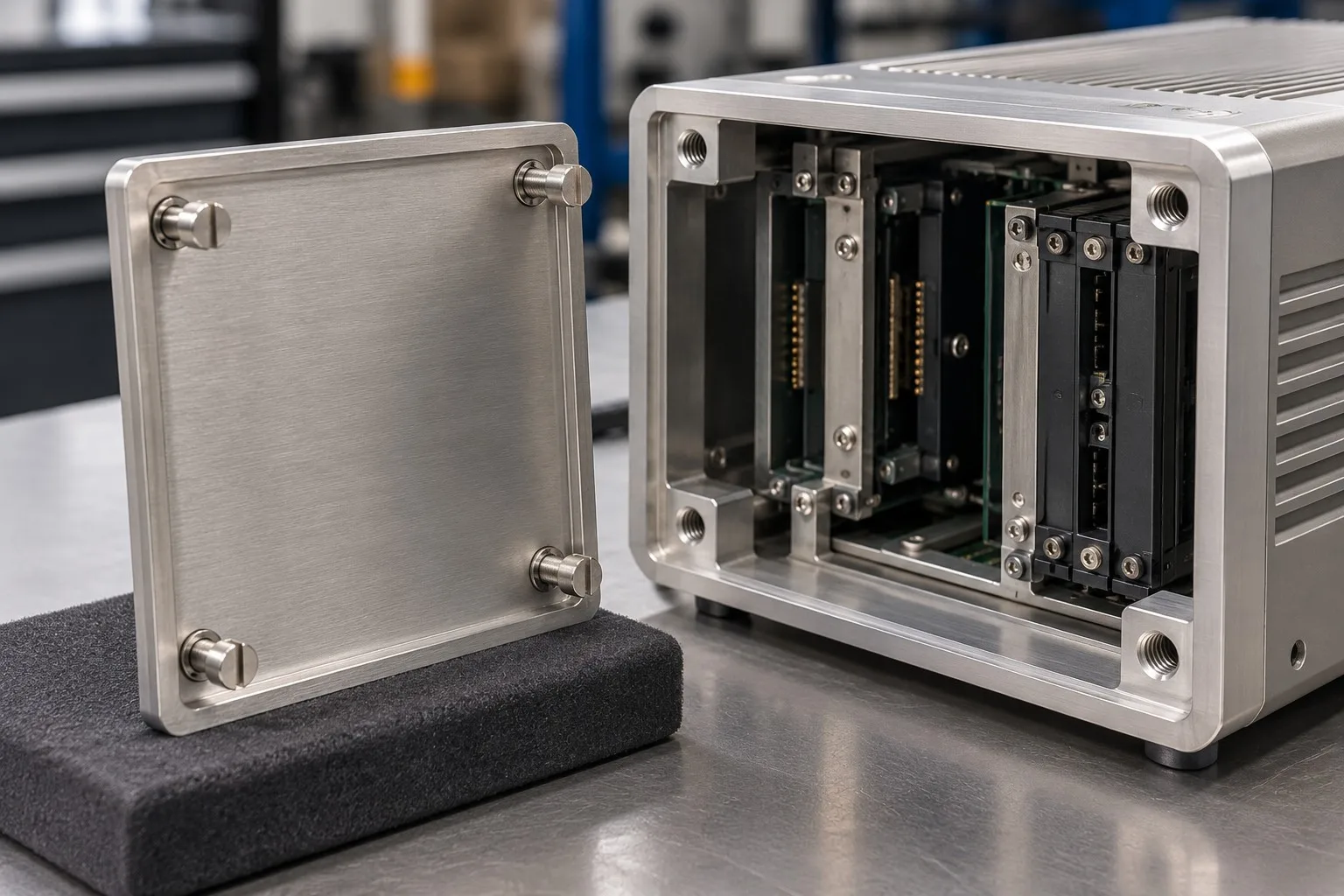
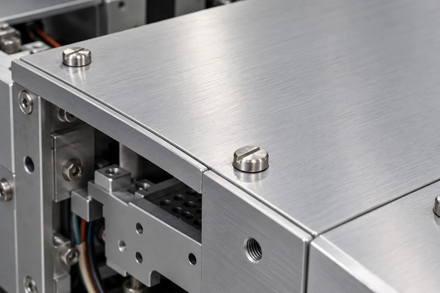
Three assembly conditions where a captive head screw keeps the cover and its hardware together, and what it has to do instead:
Medical imaging and diagnostic equipment
|
Medical imaging – retained cover hardware |
Test and measurement instruments
|
Test instruments – cover screws stay in the cover |
Laboratory and analytical equipment
|
Laboratory equipment – panels removed for cleaning |
Four reasons that matter specifically on a captive head screw, each tied to what the drawing has to prove:
|
Engineering review before the bar is cut
Head diameter, neck diameter and thread start are settled before the first bar goes on the lathe, so the first sample is measured against the drawing instead of against a guess. Basis: Drawing or sample reviewed before turning starts. |
Turned one-piece, neck in the same setup
The head, neck and shank are cut in one setup on a CNC lathe, so the neck stays concentric with the shank that slides in the panel. No joined or welded shank is used. Basis: One-piece turning route, neck cut with the head and shank. |
|
Neck and slot gauged on the part
The neck is checked for the retaining clip and the slot for the driver, so the part stays captive and can be turned after it has been backed out. Basis: Neck and slot checked with the clip and driver. |
First article to repeat production
The first article fixes the drawing revision, material heat and turning set-up; repeat orders are compared against that record. Basis: First article signed off before the batch is released. |
These captive head screws are turned from stainless bar, not assembled. The bar is cut to length, the head, neck, shank and thread relief are turned on a CNC lathe in one setup, the thread is rolled where the drawing allows it, and the part is deburred and passivated before it reaches the gauges. The operator checks the first part of every run against the drawing before the batch continues.
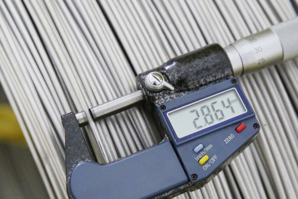
Material checked before the bar is cut |
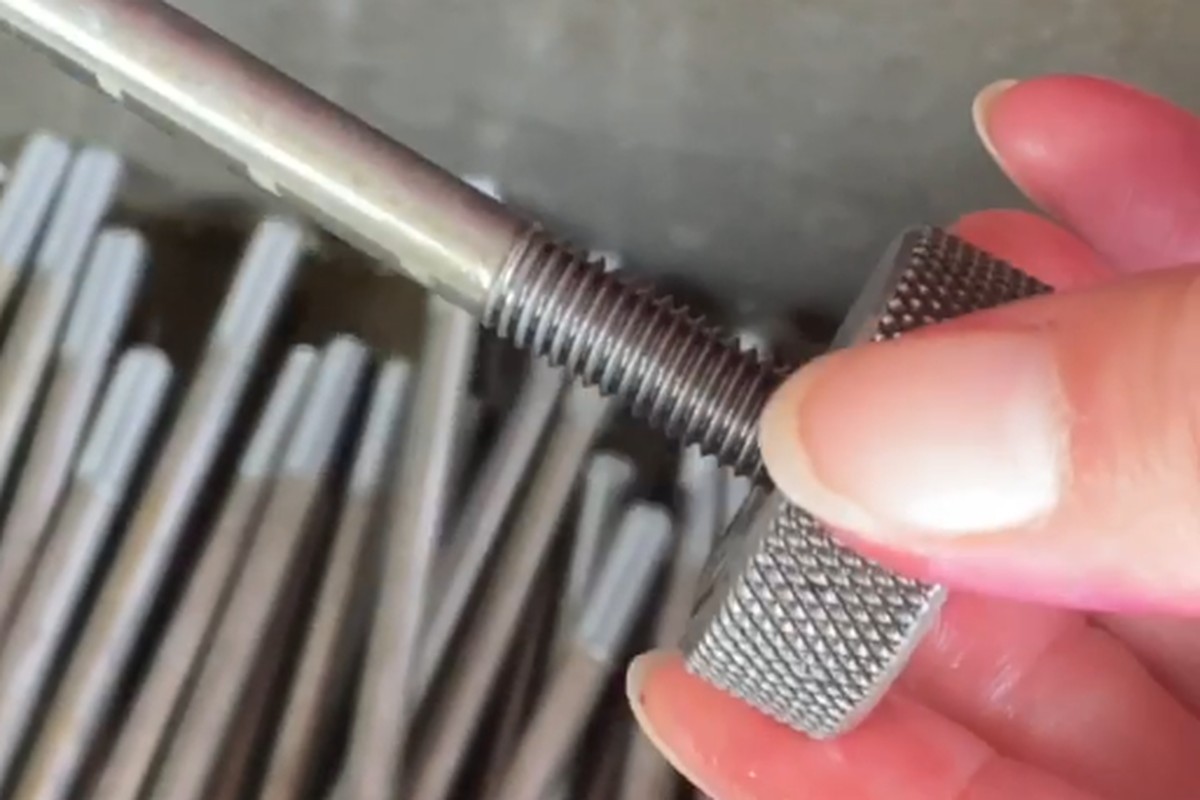
Thread gauged after rolling |
Between runs the lathe is set to the drawing head and neck dimensions; the first part goes to the gauges before the run continues, and the setting is recorded. Parts that pass the bench checks are packed in layers so the neck is not damaged, and the first article stays with the record so a repeat order can be compared with it.
What decides whether a captive head screw passes is not its appearance: it is the neck holding the clip, the slot taking the driver, and the thread matching the tapped body it engages. The inspection agreement covers those, and the criteria are the ones written on the drawing rather than a generic standard.
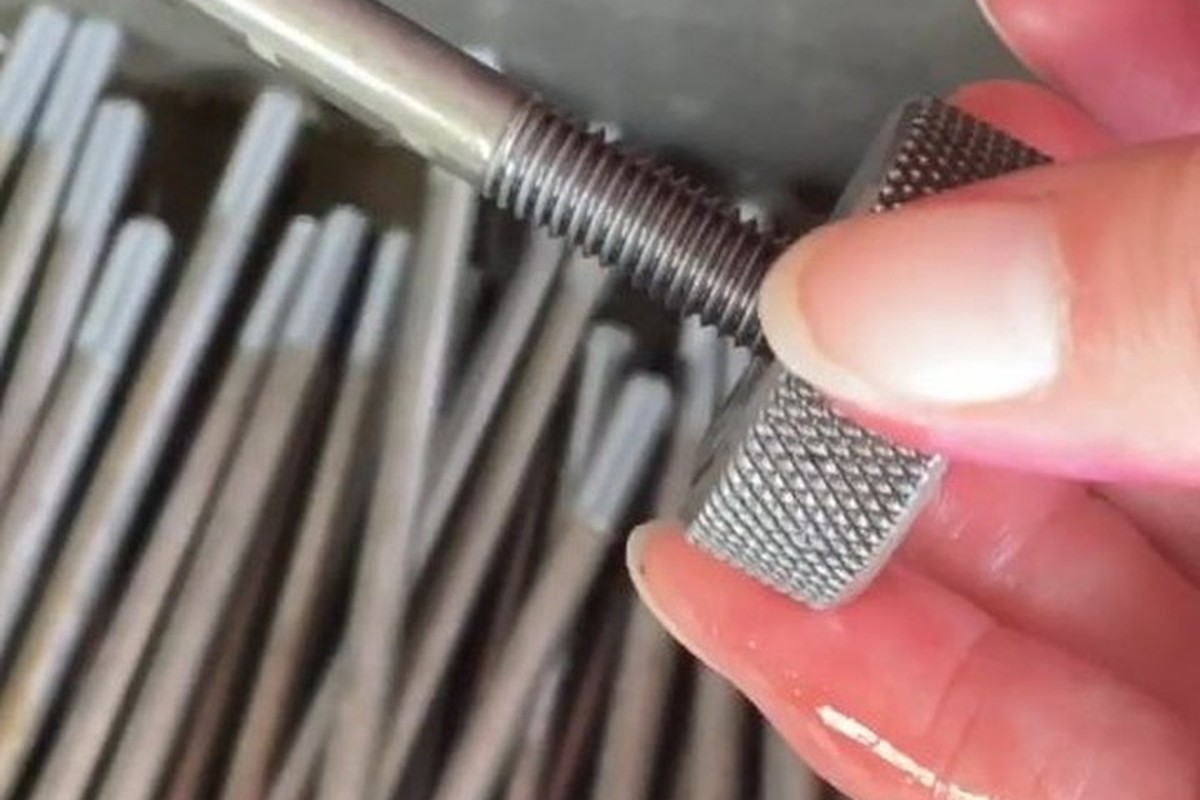
Thread gauging against GO/NO-GO gauges |
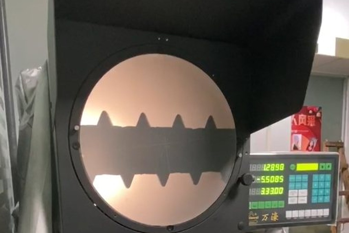
Head, neck and slot profile on the optical projector |
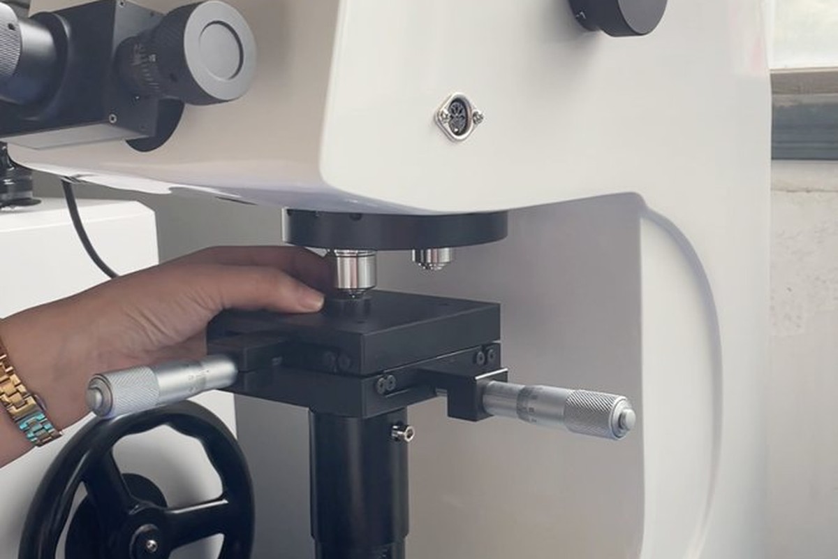
Hardness testing of the base material |
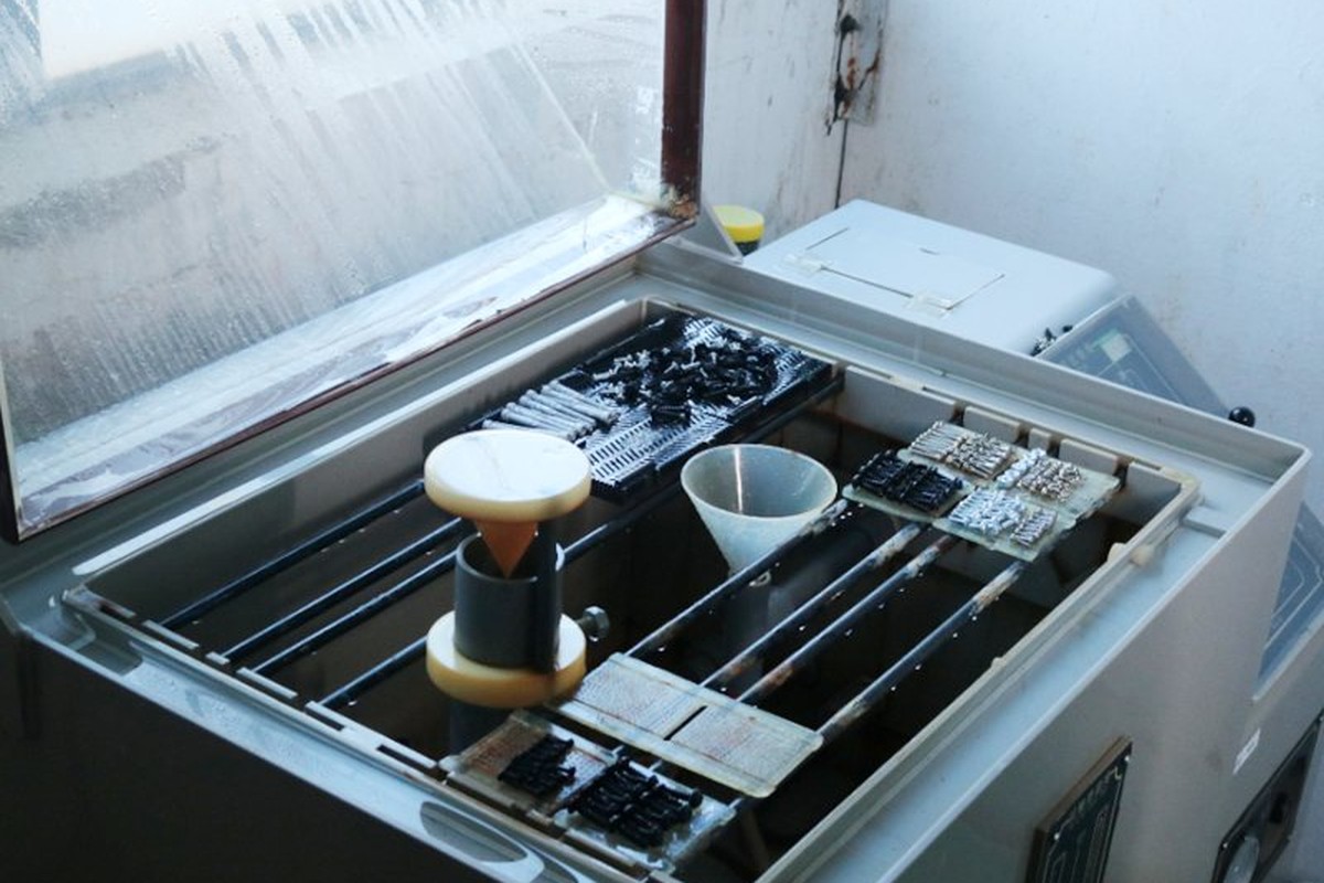
Salt-spray testing where a coating is specified |
Each batch is recorded against the drawing revision: head and neck from the first article, the slot checked with the driver, thread gauging per batch, and the material heat on the certificate. If a gauge or the slot check fails, the parts back to the last good setting are held and re-checked before anything ships.
Where a third-party report is required for the material, it is written into the drawing, the report ships with the parts and the label carries the same batch number as the inspection record.
Every captive head screw shipment is traceable to the bar it was made from. The grade, heat number and standard are recorded on the material certificate supplied with the parts, and the inspection records follow the criteria agreed on the drawing.
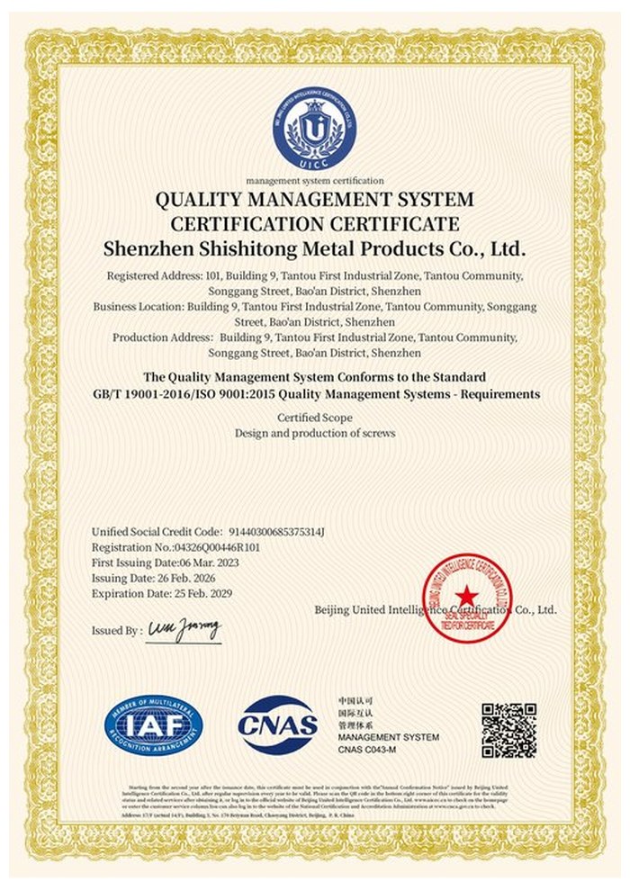
ISO 9001:2015 |
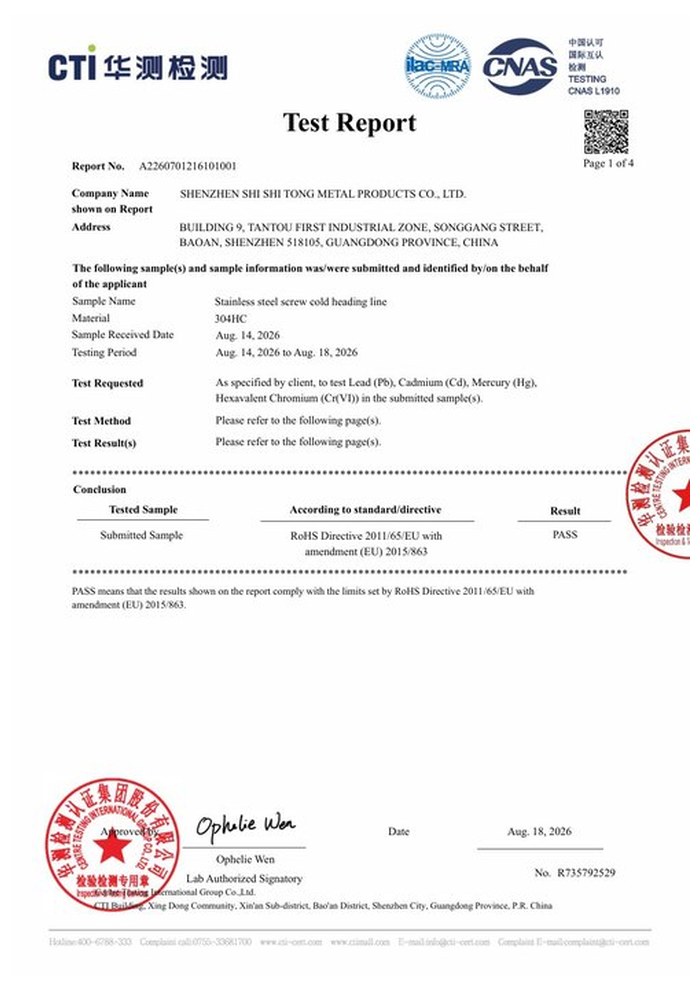
RoHS test report |
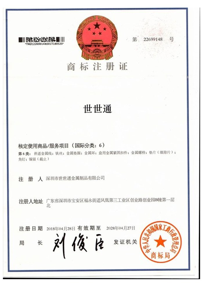
Registered trademark |
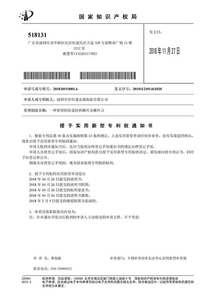
Patent: security screw and driver |
With each batch we supply the material certificate, the inspection record for the criteria on the drawing and, where it is listed, the third-party report for the material. The documents carry the drawing revision and the batch number, so the paperwork can be matched to the parts.
More than 8,678 customers in 89 countries and regions have ordered from Shi Shi Tong; 87% of orders come from repeat customers and 56% through referrals. Most projects follow the same route: drawing review, first-article approval, then batches checked against that sample. Buyers visit during the process to review samples and to see the turning, threading and finishing steps their parts will go through.
|
8,678+
customers served
|
87%
of orders from repeat customers
|
56%
of orders through referrals
|
89
countries and regions shipped to
|
Buyers and quality engineers visit for sample review, process discussion and supplier audits; the visit is arranged around production so the turning cells, the thread rolling and the finishing line can be seen on the day the parts run.

Customer group visit – sample review |

Customer group visit – process discussion |

Customer group visit – factory tour |

Customer visit – project kick-off |
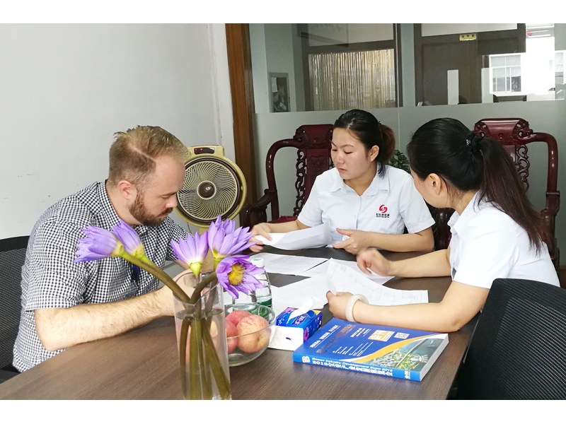
Danish customer – drawing review |
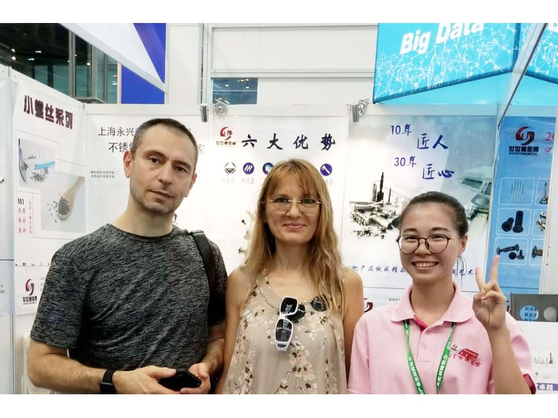
Industry exhibition – meeting customers |
It is a machine screw designed so it stays with the cover after it is unscrewed. The neck under the cap head gives a retaining clip or a slotted panel hole something to hold, so the screw pulls back and turns without leaving the cover.
Through the neck turned under the head. A retaining clip seated in the neck, or a panel slot that the neck engages, holds the screw to the cover while the thread disengages from the body behind it.
It is turned from stainless bar. The cap head, neck, plain shank and thread relief are cut on a CNC lathe, and the thread is produced after the body is turned, so the neck stays concentric with the shank.
Captive head screws are quoted from M1.4 to M12 and up to 2,000 mm, with length usually held to +0/-2 mm. Custom lengths up to 2,000 mm are subject to DFM review after drawing submission.
A flat screwdriver of the width and thickness given on the drawing. The slot is cut across the full head diameter and checked with the matching driver, so it can be turned after the screw has been backed out of the body.
Thread size and pitch, thread length and position, plain shank length, total length and datum, head diameter and height, neck diameter and length, slot width, material grade, surface condition, and quantity.
How a captive head screw project runs from drawing to repeat delivery:
|
1
Send the drawing or sample
|
→ |
2
DFM review and quotation
|
→ |
3
First article approval
|
→ |
4
Batch production and repeat orders
|
Each step is confirmed with you before the next one starts; the drawing revision from the first article is what repeat orders are checked against.
For a captive head screw quotation, send the drawing with thread size and position, plain shank and total length with its datum, head diameter and height, neck diameter and length, slot width, material grade and surface condition. Head, neck and slot are confirmed with you before production.
|
Thread size, pitch and length
|
Plain shank and total length
|
Head diameter and height
|
|
Neck diameter and length
|
Slot width
|
Material grade and quantity
|
Sending a drawing? The form below does not take attachments. Email the PDF, DXF or STEP file to sst@szsst88.com with the part name and quantity in the subject line – the drawing is reviewed and a quotation follows.

 +86 13143444311
 sst@szsst88.com