Tel:
+86 13143444311
Email:sst@szsst88.com
Fax:+0086-755-27322278
Address:Building 9, First Industrial Zone, Tantou Industrial City, Songgang Street, Baoan District, Shenzhen 518105, Guangdong, China
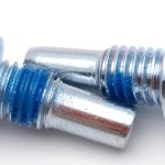
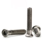
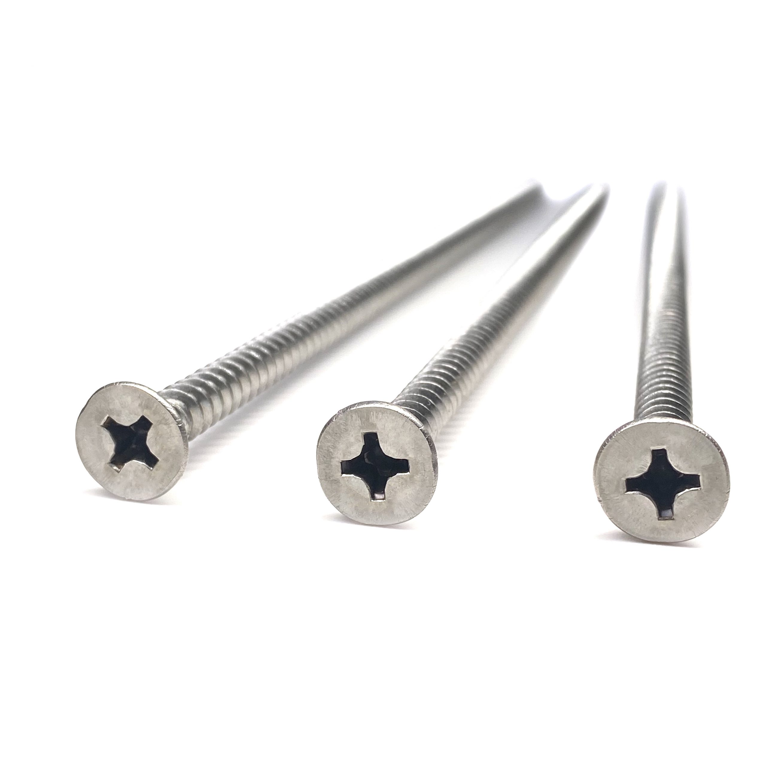
Type:Countersunk long self-tapping screw
Materials:Stainless steel (304 / 316 per drawing)
Surface treatment:Plain, cleaned (no coating)
Head Type:Countersunk (flat) head, 90°
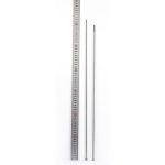
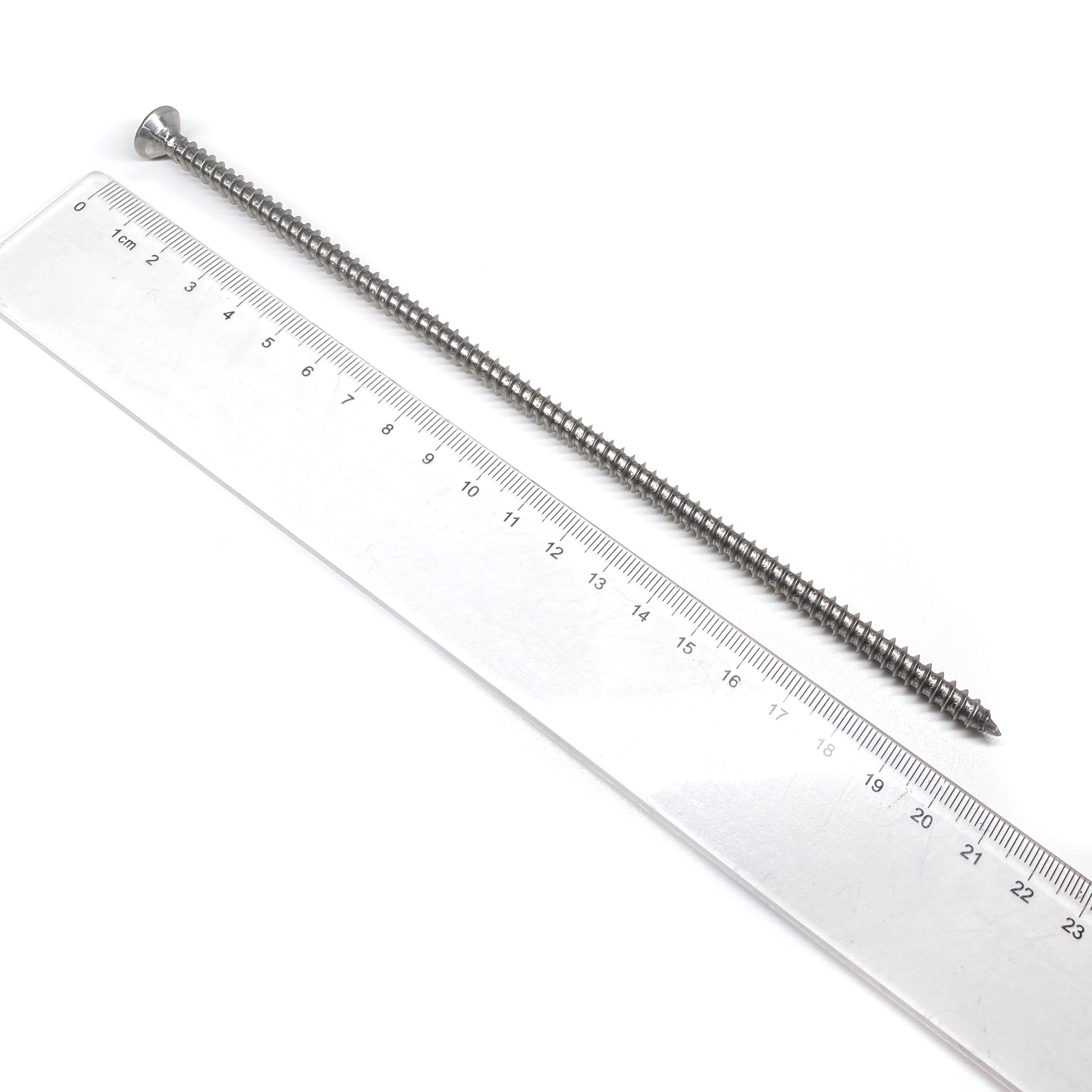
Size:M4 × 205 mm
Drive type:Phillips (cross recess), PH2
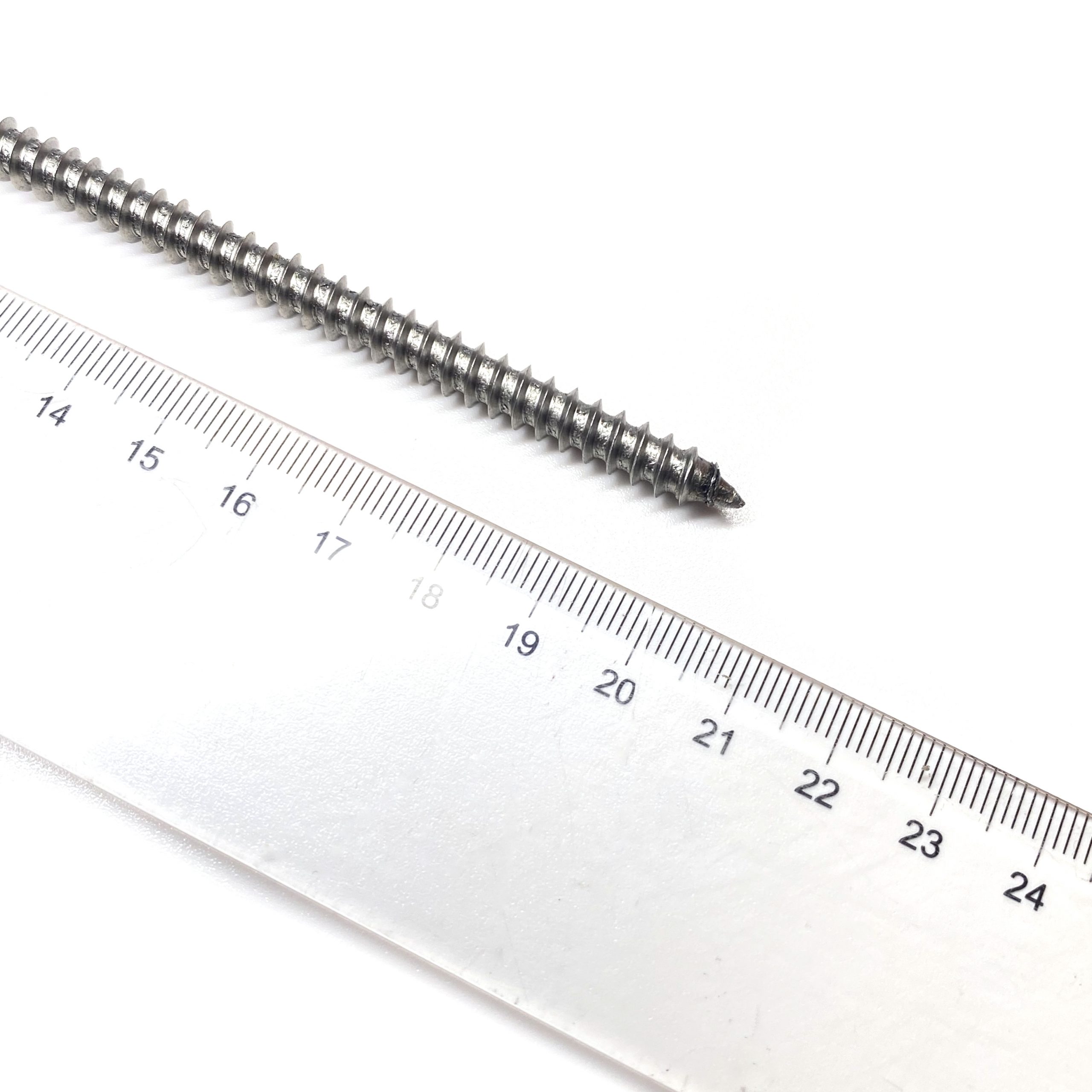
Thread:Coarse self-tapping thread, full length
Tail feature:Gimlet point, sharp
Forming:Split-die cold heading; thread rolled full length
Number:1014
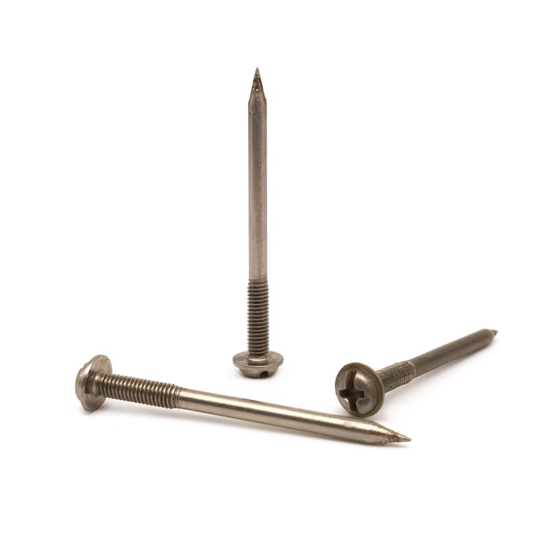
This is an M4 stainless steel countersunk screw, 205 mm long, with a coarse self-tapping thread running from under the head to a sharp gimlet point and a Phillips cross recess in a 90° flat head. The head is formed on a split die, the thread is rolled over the full length, and the shank is straightened before packing. The length is what separates this part from a 20 mm screw of the same head and thread: driver, thread and head all sit on a load path ten times longer, and every one of them behaves differently because of it.
|
Material
Stainless steel, 304 / 316 per drawing
|
Head
Countersunk, 90°, flush seat
|
Drive
Phillips cross recess, PH2
|
|
Thread
Coarse self-tapping, full length
|
Length
205 mm overall, M4 nominal
|
Finish
Plain, cleaned, no coating
|
Send Your Drawing for a Drive and Seat Review
It is a headed screw with a flat, 90° countersunk head, a cross recess, a coarse thread that runs the whole way from the bearing face to the point, and a gimlet point at the end. It forms its own mating thread in the material it enters, so it is not a machine screw: a machine screw follows a thread that already exists. It is not a self-drilling screw either, because there is no drill point on the tip and a pilot hole is required before it can start. And it is not a shoulder screw, because the diameter under the head is threaded rather than ground to a pivot fit.
Those distinctions matter because of the length. On a 20 mm screw the head, the thread and the driver are close enough together that a problem in one is felt immediately in the others. At 205 mm they are separated by a long elastic column: the driver turns at one end, the thread works at the other, and the head decides how the whole assembly sits on the panel.
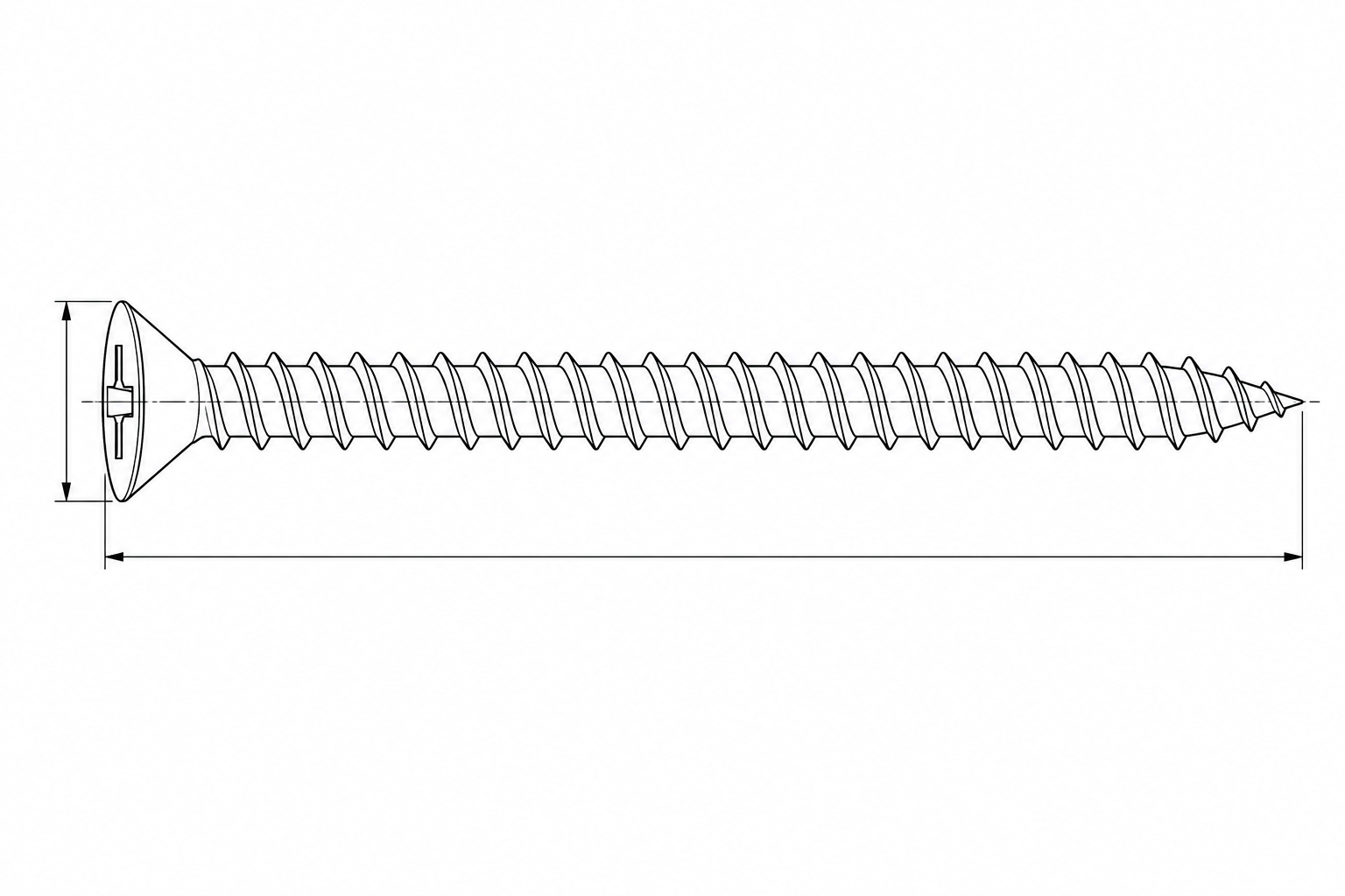
The four dimensions that decide this part: head angle and diameter, overall length, thread length and point form.
A coarse self-tapping thread at this diameter runs at roughly a 1.4 mm pitch, so a 205 mm thread is about 146 turns of engagement. A 25 mm screw of the same family is about 18 turns. Every one of those turns forms a new piece of mating thread, and every one adds friction: between the thread flanks and the material, and between the screw and the hole wall behind it. The driver does not feel 146 separate events – it feels the sum.
That sum is why a long self-tapping screw needs a different assembly plan from a short one. Drive torque climbs as the engaged length grows, and in stainless steel the work of forming the thread also work-hardens the surface it is sliding against. Heat builds at the flanks, friction rises further, and the recess in the head – the smallest feature in the load path – takes the consequence. A joint that is tightened by feel at 25 mm is not repeatable at 205 mm.
What the drawing should fix, and what we hold on our side: pilot diameter and depth, the engaged thread length the joint actually needs, the drive method and clutch setting, any lubricant, and whether the thread is expected to form or to cut. We control pitch, core diameter, flank finish and the concentricity of point to thread, because those are the variables that decide how much of the driver’s torque reaches the material instead of being burned as friction.
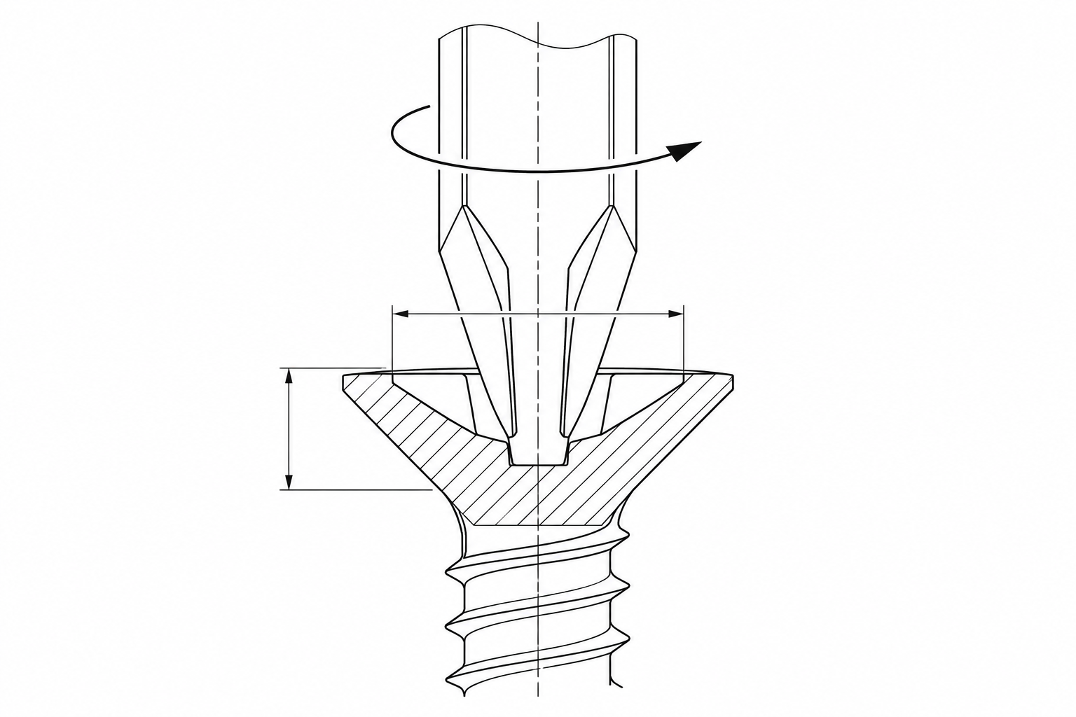
The recess is the smallest feature in a 205 mm load path, and the first place a rising drive torque shows.
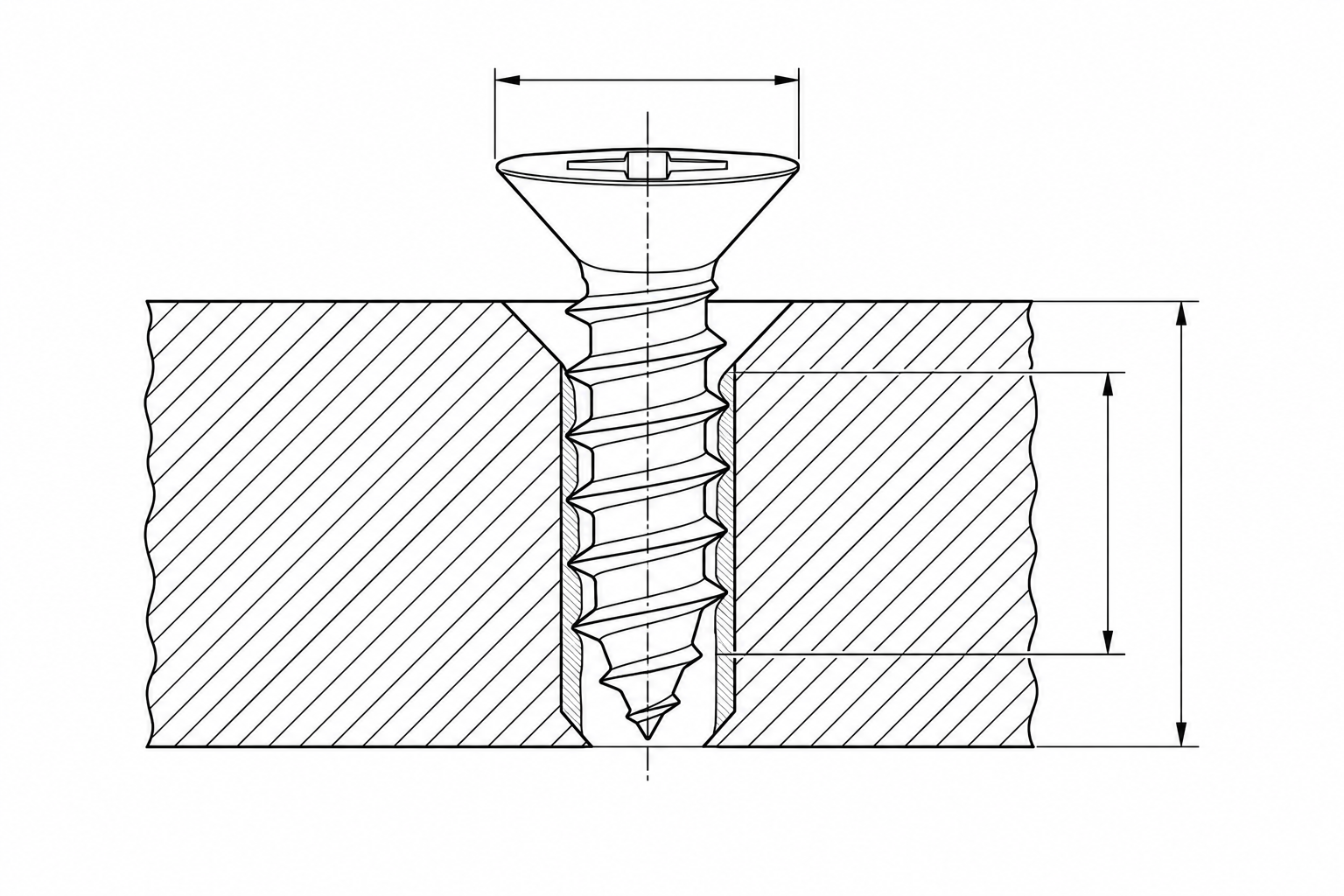
A countersunk head only sits flush when three dimensions agree: the head angle, the head diameter and the depth of the countersink in the panel. Match all three and the cone bears on a full ring, the head face finishes level with the surface, and the clamp load spreads over an area large enough that the panel does not dish. Miss the angle by a couple of degrees and the contact collapses to a line: the head stands proud on one side, the panel is loaded unevenly, and the joint looks seated while it is not.
Head thickness against panel thickness is the second half of the same agreement. In a thin panel, a countersink deep enough to swallow the head can leave very little bearing ring, and the 205 mm screw will pull that ring down into the hole. In a thick or composite panel the countersink has to be cut to the head diameter, not to a nominal size, or the head will sit in a pocket that is too wide and the screw will centre itself wherever the thread takes it.
We hold head angle, head diameter, head thickness and the runout of the bearing face to the shank. Those are the four numbers that let a customer cut one countersink program and have every screw in the batch finish flush.
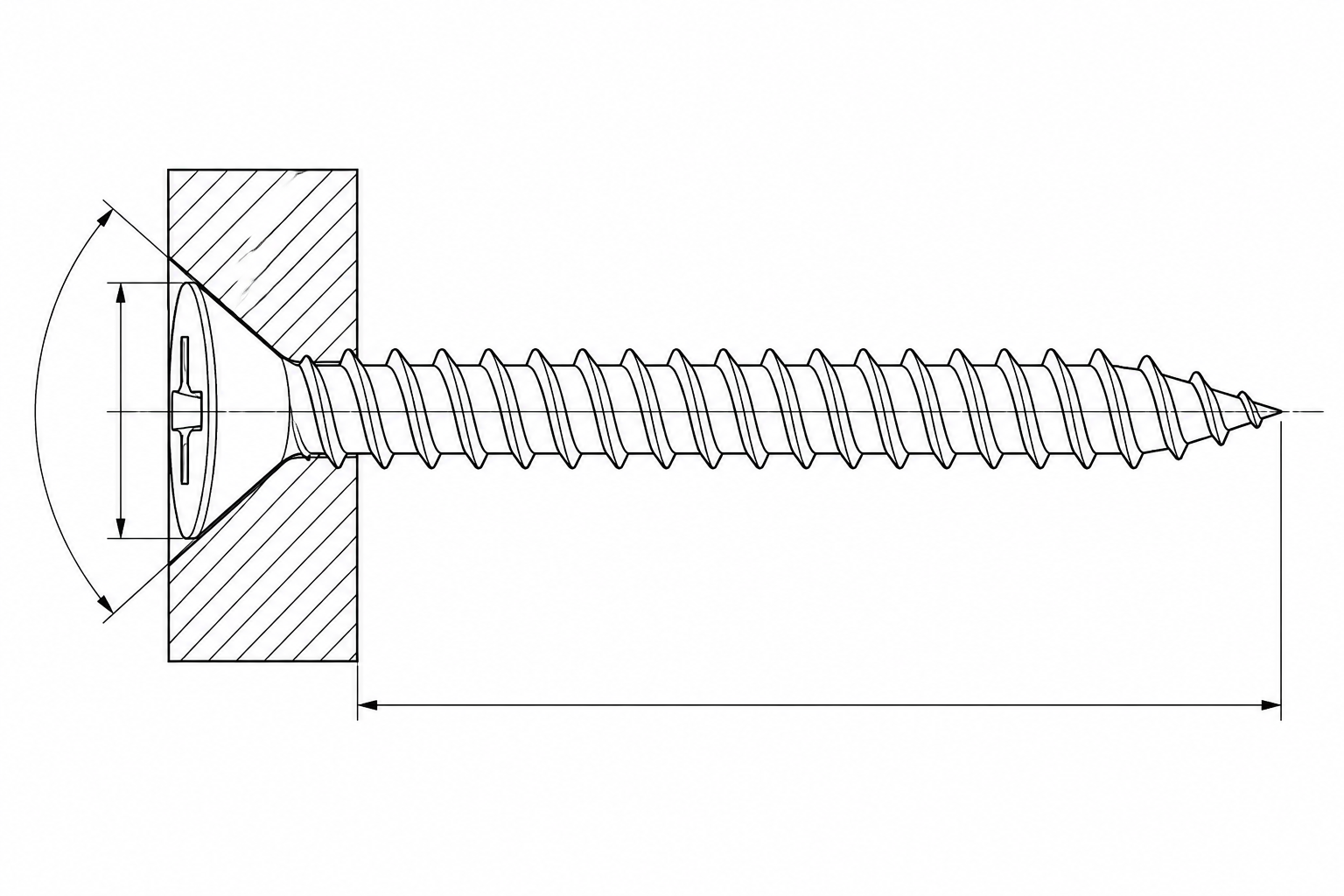
Seat geometry: angle, head diameter and countersink depth have to agree before the head can finish flush.
A self-tapping screw does not find a thread; it makes one. The pilot hole is smaller than the thread diameter and usually close to the core diameter, so the first turns press or cut the material into the space between the flanks. Engagement depth, and therefore pull-out resistance, is set by the difference between the pilot hole and the core, not by how hard the driver is pushed.
That relationship has two failure modes, and they pull in opposite directions. A pilot hole that is too small makes the screw do too much work: torque spikes, a moulded boss splits at the wall, and the recess cam-outs before the head seats. A pilot hole that is too large leaves shallow engagement: the thread strips at a low load, and a joint that felt tight lets go under vibration.
At 205 mm the screw also has to travel a long way before the thread reaches the working section. In a deep moulded boss that means the point must stay centred for the whole entry, which is a straightness and point-concentricity question as much as a thread question. On a multi-plate stack the thread has to pass through clearance holes without cutting them, and only engage where the drawing says it should.
Engagement is set by pilot diameter against core diameter – not by drive force.
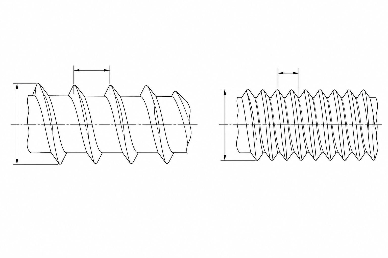
Coarse self-tapping thread against a machine thread: the wider pitch and the deeper flank are what let it form its own mating thread.
A gimlet point is a short cone that starts the thread. Its length is small – a few millimetres – but in a blind hole it decides whether the joint closes. If the hole is shallower than the thread length plus the point, the point reaches the bottom before the head reaches the panel. The driver then tightens against the hole bottom rather than against the joint: torque reads normal, the head stands proud, and the connection is preloaded in the wrong place.
The second requirement is concentricity. A point that runs off the thread axis starts the cut at an angle, and over 205 mm that angle is carried into every thread behind it. The screw walks, the hole is enlarged on one side, and pull-out falls away. We check point form and point-to-thread runout as a pair, and we check the point length against the drawing so a customer’s blind hole can be dimensioned with a known clearance.
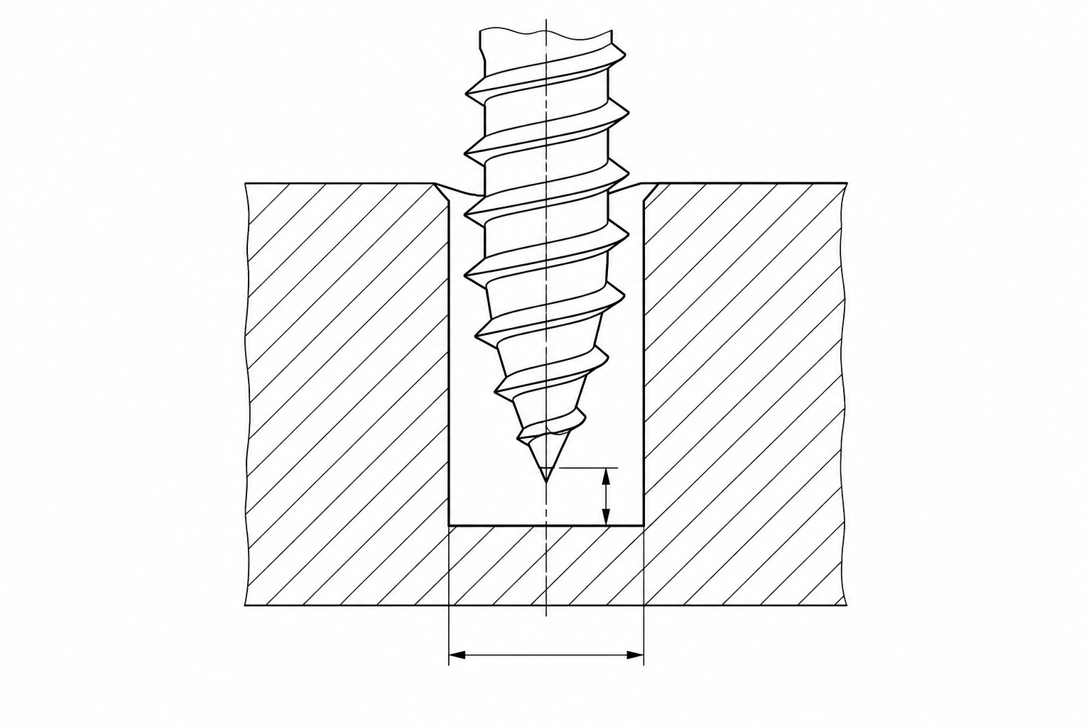
Blind-hole seating: the point needs clearance at the bottom, or the head never reaches the panel.
A screw this slender is a column before it is a fastener. If the shank bows, the point arrives at the hole off-axis, the thread starts at an angle, and the head pulls the panel towards wherever the bow points. The joint tightens, but the panel is distorted and the thread is loaded on one flank.
Straightness is therefore a drawing figure, not an impression. It is agreed either as a deviation over a stated length or as total runout over the full 205 mm, measured between centres rather than by rolling the part on a bench. Parts are straightened after rolling and packed so the figure survives transport; a long screw that arrives bowed has lost the tolerance it was bought for.
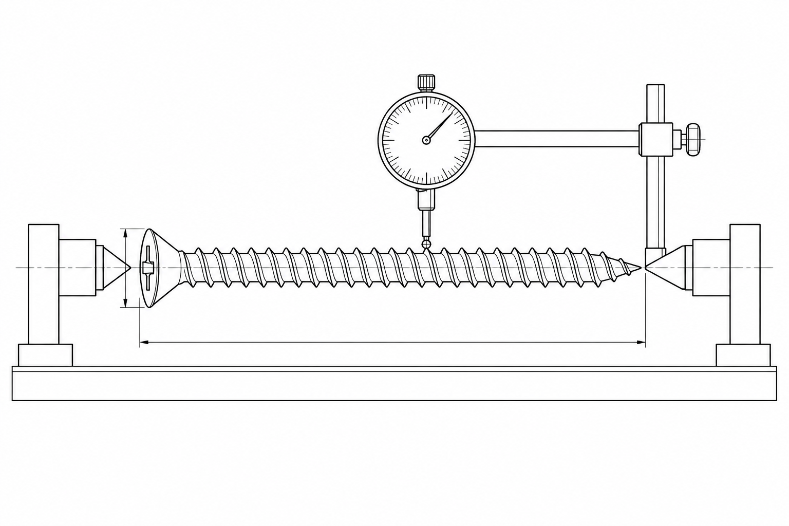
Straightness is measured between centres over the full length, not judged by eye.
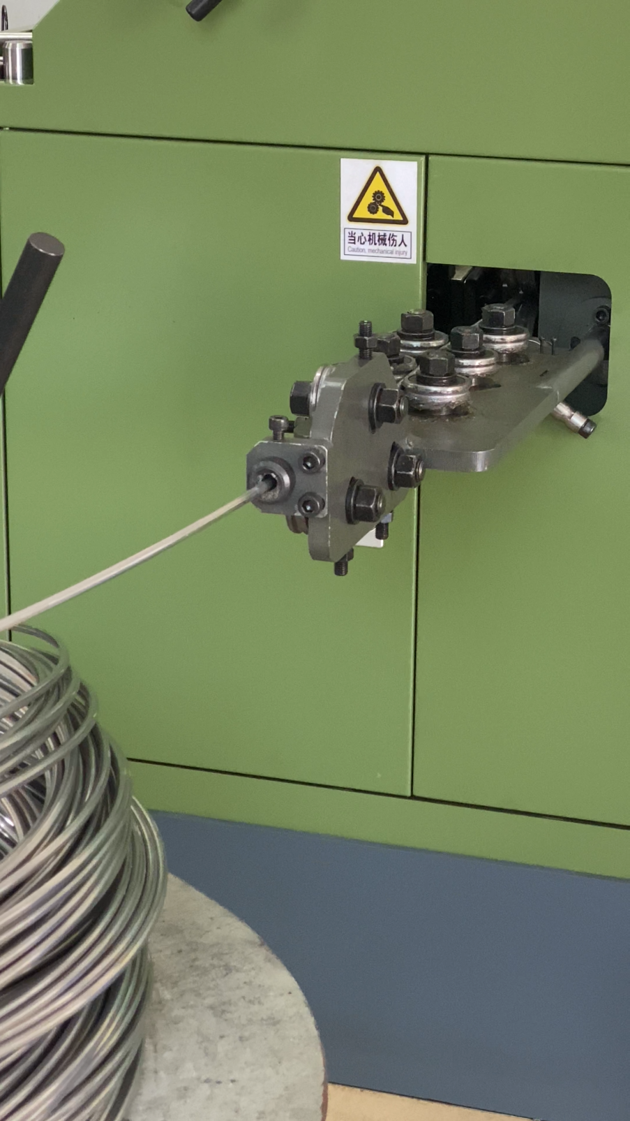
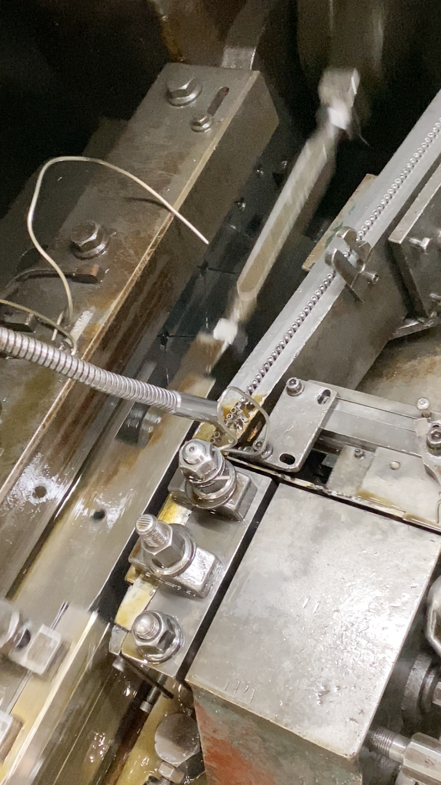
The screw is made from wire in one piece. Wire is cut to length, the countersunk head is formed between two half-dies that open to release a shank far longer than any single die cavity, the thread is rolled over the full 205 mm with long dies, and the part is straightened, cleaned and inspected. There is no welded joint anywhere in the length: the head and the point belong to the same piece of wire.
Two steps carry the risk on this part. Heading sets the head angle, the head diameter and the recess in one stroke, so a die that is slightly off shows up as a recess that is not concentric with the shank – visible later as a driver that rocks. Rolling over the full length is a straightness operation as much as a thread operation: the dies must support the shank while the thread is formed, or the part leaves the machine with a bow that no inspection can remove.
|
1
Wire cut
to length |
→ |
2
Split-die
heading |
→ |
3
Recess
formed |
→ |
4
Full-length
thread rolling |
→ |
5
Straightening
and check |
→ |
6
Cleaning
(plain finish) |
→ |
7
Dimensional and
thread inspection |
→ |
8
Supported
packing |
Route for the 205 mm screw: head, recess and thread are formed on the same piece of wire, then straightened and packed so the length arrives straight.
MANUFACTURING
Heading, rolling and straightening under one roof
One team owns the die, the rolling setup and the straightness figure, so a change to the head or the thread is reviewed by the people who run the machine.

 |
 |
|
1998
Manufacturing since
|
M1.4–M12
Long screw diameter range
|
2–2000mm
Long screw length range
|
89
Countries and regions
|
Die design, rolling setup and inspection criteria are agreed before the first sample, and the same team follows the part into repeat production. See our factory.
Inspection on this part is dominated by relationships rather than single dimensions: head angle against the seat, recess position against the shank axis, thread gauge against the full length, point form against the thread, and straightness over the whole 205 mm. A screw can pass every individual dimension and still fail in assembly if the recess is not concentric or the shank is bowed.
INSPECTION
Head, recess, thread and straightness measured per batch
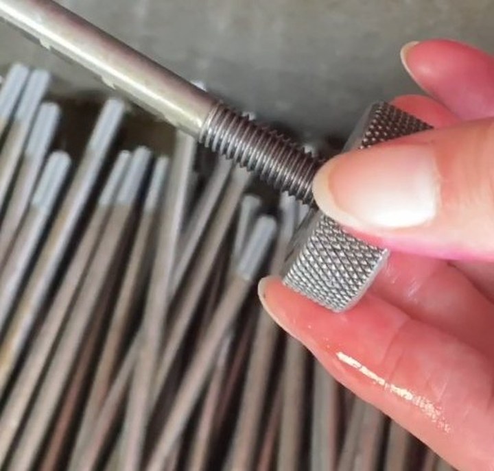
GO / NO-GO thread gauging over the full thread length |
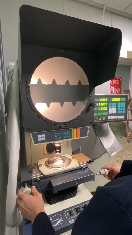
Head angle, recess position and thread profile on the projector |
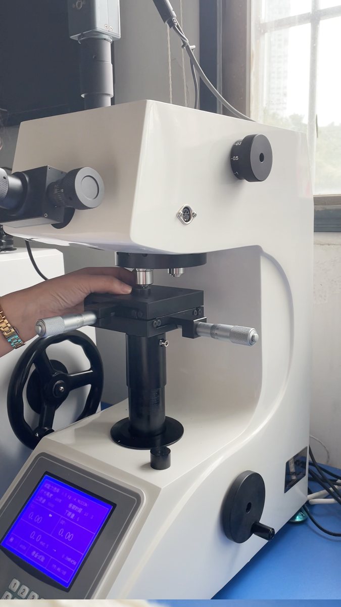
Hardness testing where the drawing specifies a condition |
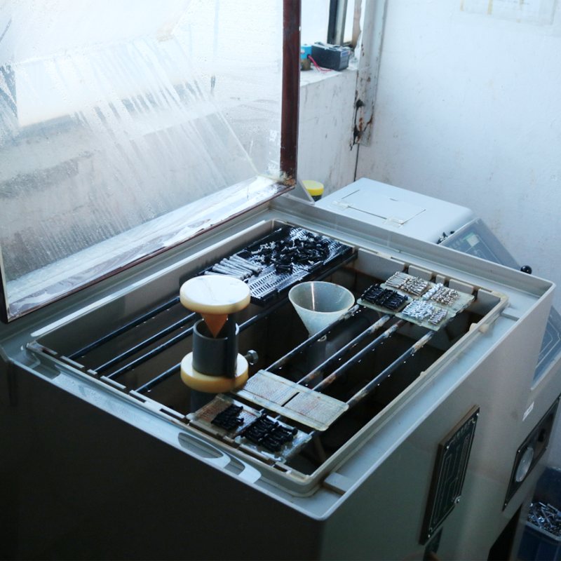
In-house salt-spray testing for selected finishes |
Inspection follows the drawing and the agreed inspection plan; records are kept per batch, and in-house salt-spray results are reported separately from third-party test reports.
|
Head angle and diameter – projector and calliper against the drawing, checked as a seat geometry, not a cosmetic feature.
|
Recess position – concentricity of the cross recess to the shank axis, which decides whether the driver rocks.
|
|
Thread – GO/NO-GO gauges along the full 205 mm, plus pitch and flank check on the projector.
|
Point – form and length checked against the drawing so a customer’s blind hole has known clearance.
|
|
Straightness – measured between centres over the full length, recorded as a figure rather than a pass/fail impression.
|
Material – grade and heat number recorded against the batch and carried into the material certificate.
|
Paperwork is issued per batch so the file matches the screws in the box: material certificate for the wire lot, dimensional report including head angle, recess position and straightness, thread gauge result over the full length, and the finish record for a plain cleaned part.
CERTIFICATES
Quality and compliance documents
Click any document to open the full-size file.
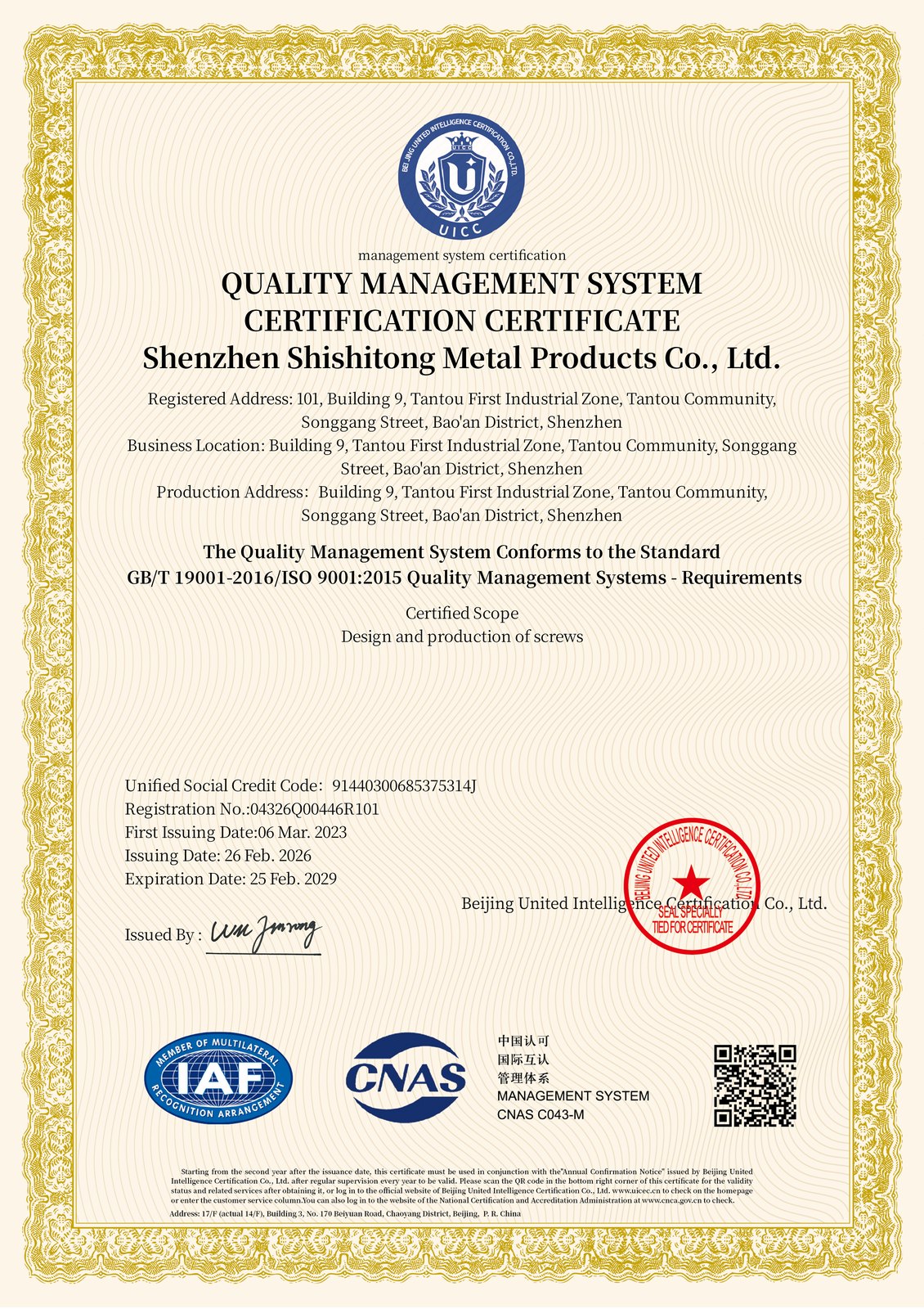
ISO 9001:2015 |
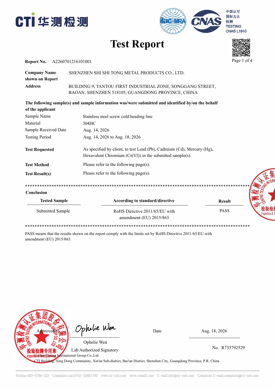
RoHS test report |
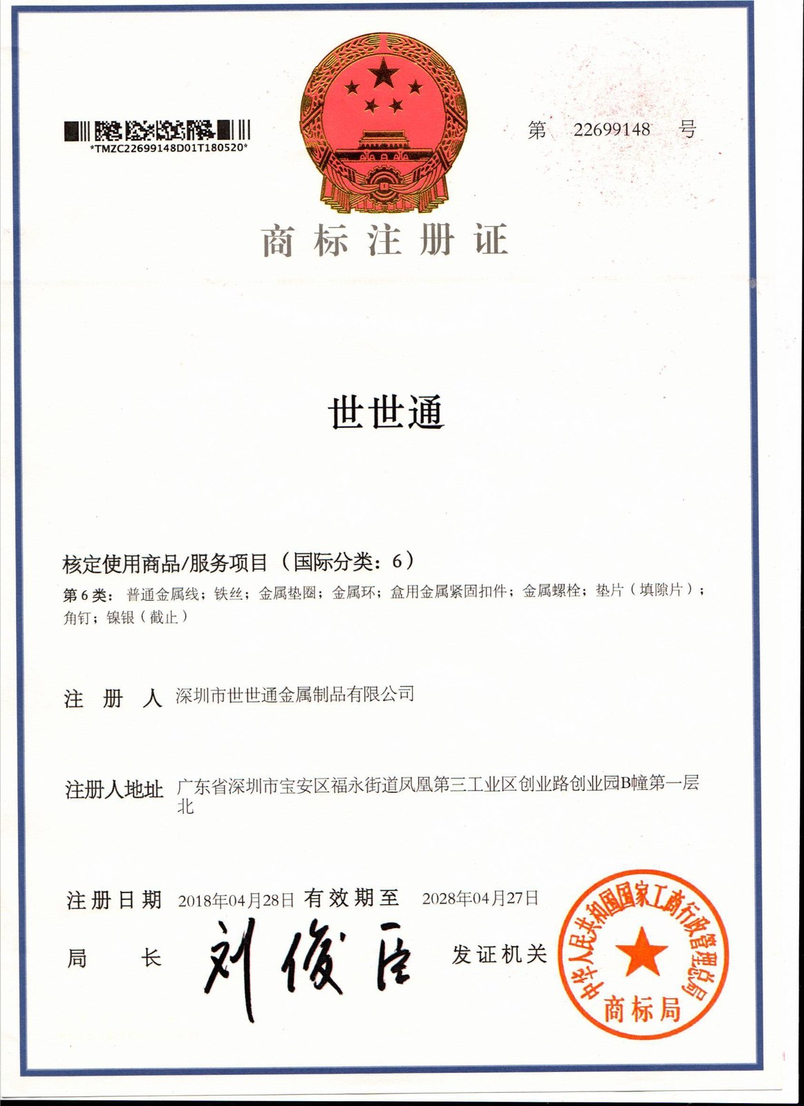
Registered trademark |
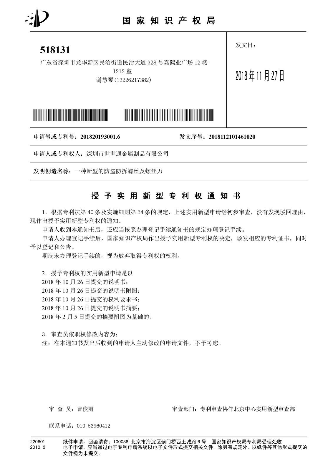
Patent – security screw and driver |
Material grade and heat number, the dimensional report, the thread gauge result and the approved sample reference are issued with the order. Certificates and sample reports are published in full on the quality documentation page.
A 205 mm self-tapping screw is chosen where a joint has to be closed from one side, through a deep stack, with the head finishing flush on a visible face. The three assemblies below are the ones this geometry is most often drawn into, and the failure mode is different in each.
The problem. Module frames and cover plates inside a fixed cabinet are clamped through deep moulded standoffs. A screw that stops short leaves the module loose against its neighbour; a screw driven past the standoff cracks the moulding, and the crack only shows at the next service visit, when the cover comes off.
What the length changes. At 205 mm the thread is engaged along the whole standoff, so the driver is forming thread for the entire travel and the torque it reads is the sum of that work. Moulded plastic also creeps: a joint closed on a high torque relaxes over time, and the clamp load that was measured at assembly is not the clamp load in service.
What we control. Pitch and core diameter held so engagement in the standoff repeats from screw to screw; straightness and point concentricity so the screw finds the boss instead of cutting across it; a head angle that lets the cover plate sit flush; and a plain finish with no coating to flake into the module compartment.
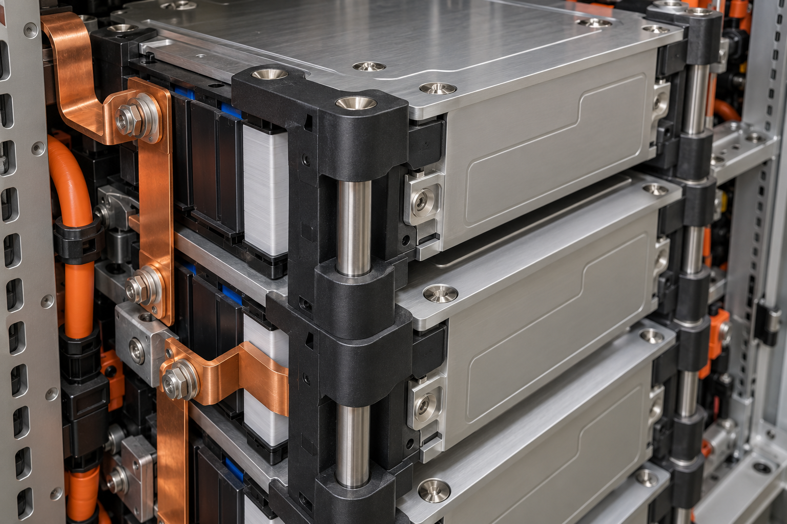
Module frames clamped through deep moulded standoffs – the joint closes from the cover side, and the head finishes flush.
The problem. A moulded panel stack sits over a metal chassis, the heads have to finish flush on the outer panel, and the instrument is opened for service several times in its life. Every reassembly runs the thread through the same boss again.
What the length changes. A long thread re-entered by hand is easy to start cross-threaded, and stainless on stainless galls at the flank. A thread that cuts a new path on every service loses pull-out each time, and the panel that was flush when the instrument shipped stands proud by the third visit.
What we control. A 90° head angle and a head diameter that match a single countersink program; rolled thread flanks with a finish that resists galling on repeated assembly; straightness so the screw enters the boss square; and 304 or 316 as the cleaning chemistry requires.
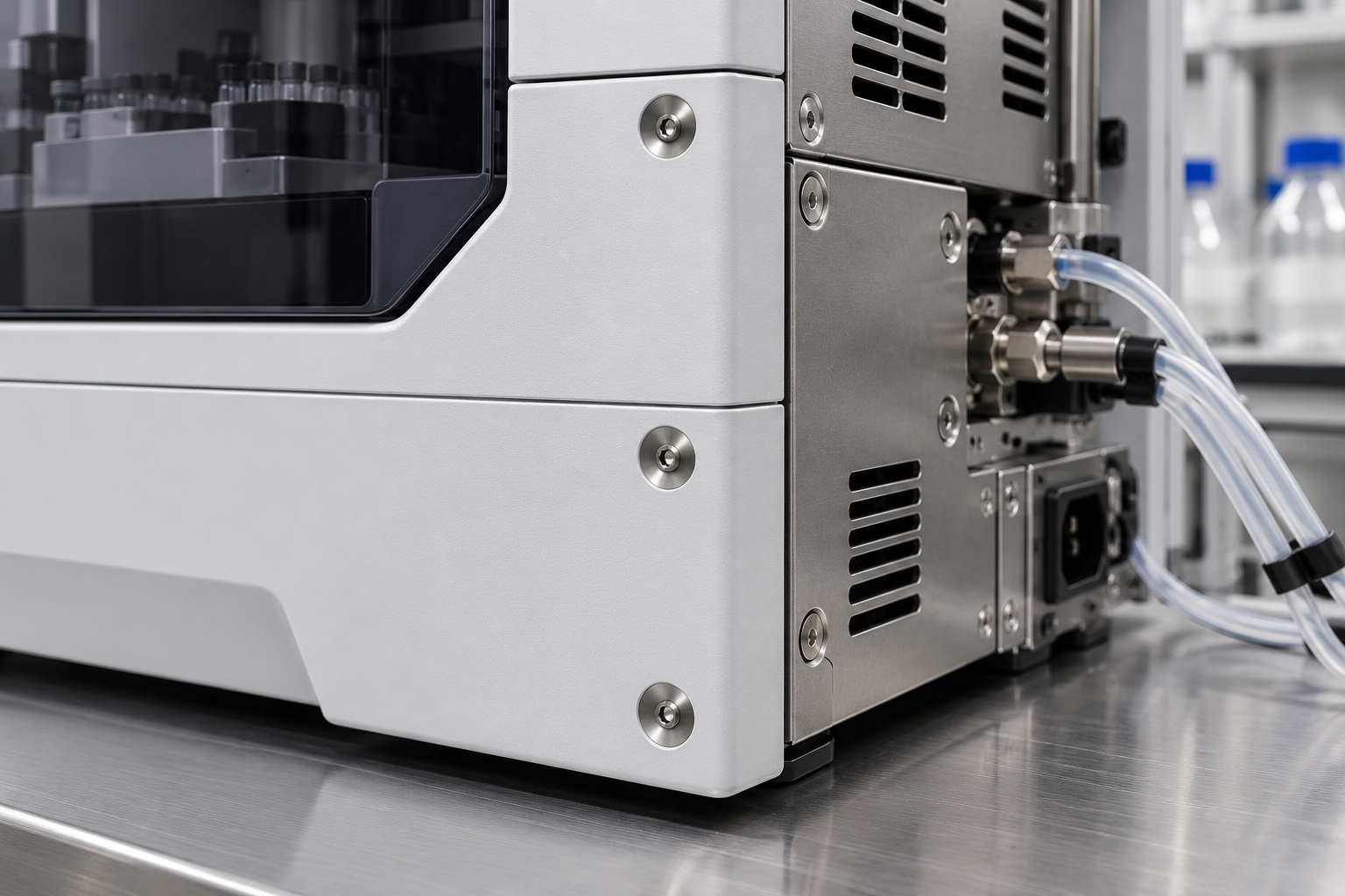
Panel stack over a chassis: the heads finish flush, and the same bosses are re-used at every service visit.
The problem. Stainless cladding and tray brackets are washed down, and anything that holds water holds soil. A head standing proud of the panel is a ledge; a recess full of standing water is worse.
What the length changes. A flush seat removes the ledge, but the seat has to be formed without dishing a thin sheet. Over 205 mm the screw reaches brackets and frame members well behind the cladding, so the thread is working in a different material from the one the head bears on – and the two have to be dimensioned together.
What we control. Head geometry that seats flush without pulling the sheet down; a coarse thread that forms cleanly in the frame material; plain 304 or 316 with passivation where the drawing calls for it; and a recess that drains and can be cleaned.
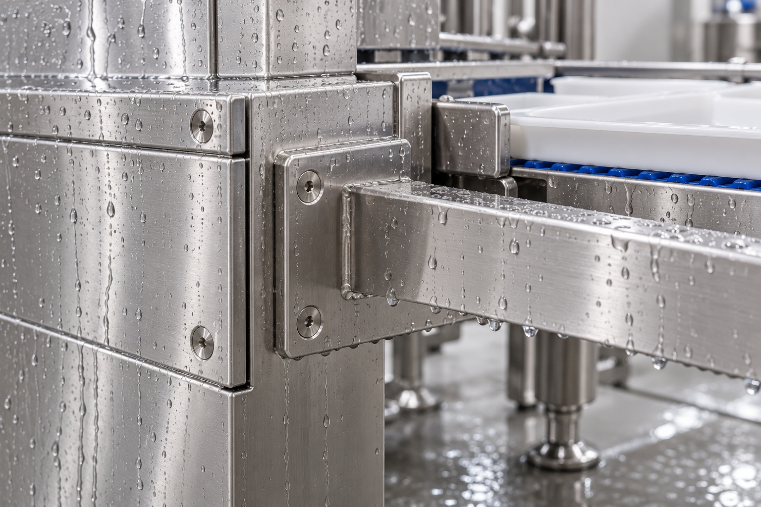
Cladding and brackets on a washdown line: flush heads, and a recess that drains.
A coarse self-tapping thread of this type forms its own mating thread in the pilot hole: sheet metal, moulded plastic, composite or a cast boss, depending on the drawing. The pilot diameter and the boss wall are set by the joint, and we hold the pitch, core diameter and point so the engagement that the drawing asks for is repeatable.
Because the joint closes progressively through a deep stack. A full-length thread lets the screw keep engaging as it travels, which is what holds a long standoff or a multi-plate stack together. The cost is torque: about 146 turns of engagement at a coarse pitch, so the driving method has to be planned as carefully as the thread.
Yes, if the countersink depth matches the head thickness and enough bearing ring is left. In a thin sheet the countersink can remove most of the material under the head, and the clamp load then dishes the panel. Send the panel thickness with the drawing and we will check the head geometry against it before quoting.
It will if the drive is planned. A PH2 bit that is worn, or held at an angle, loads two corners instead of four flanks and cam-outs long before the head seats. We hold recess depth, position and the condition of the recess walls; the assembly side holds bit condition and a clutch setting that stops at the seat rather than at a torque figure.
Straightness is agreed as a figure over a stated length, or as total runout over the full 205 mm, and it is measured between centres rather than by rolling the part on a bench. Parts are straightened after rolling and packed in a way that supports the shank, because a long screw that arrives bowed has lost the tolerance it was bought for.
Yes. Grade is taken from the drawing: 304 for general indoor equipment, 316 where the part sees chlorides, cleaning agents or washdown. State the grade, the surface condition and any passivation requirement, and the material certificate follows the batch.
The drawing with head angle and diameter, head thickness, recess type, nominal diameter and pitch, overall length, thread length, point form, the pilot hole or boss the thread will form into, material grade, surface condition, straightness requirement, and the drive method at assembly – plus quantity and how the part is packed.
Shi Shi Tong has manufactured custom screws since 1998, including long screws formed to a customer drawing. Engineering support covers drawing review, die and rolling planning, straightness agreement, sampling and repeat production, so a change to the head angle, the recess or the thread is reviewed by the team that builds the die.
CUSTOMERS
Buyers who visit before they place the order
Programmes start with a drawing review and a plant visit, not with a catalogue page.
|
8,678+
Customers served, cumulative
|
87%
Returning-customer order share, all channels
|
56%
Order share from referrals
|
89
Countries and regions
|
Send the drawing with head angle and diameter, head thickness, recess type, nominal diameter and pitch, overall length, thread length, point form, the pilot hole or boss the thread forms into, material grade, surface condition and the straightness figure. We review the seat geometry and the drive against your assembly first, then quote the part and the inspection plan against the quantity you actually order.
|
Drawing with head angle, diameter and thickness
|
Nominal diameter, pitch and thread length
|
Pilot hole or boss the thread forms into
|
|
Overall length and point form
|
Material grade and surface condition
|
Straightness requirement and drive method
|

 +86 13143444311
 sst@szsst88.com