Tel:
+86 13143444311
Email:sst@szsst88.com
Fax:+0086-755-27322278
Address:Building 9, First Industrial Zone, Tantou Industrial City, Songgang Street, Baoan District, Shenzhen 518105, Guangdong, China
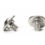
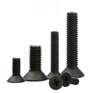
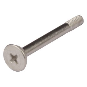
Type:Phillips Countersunk Head Screw, Stainless Steel Micro Screws
Materials:Stainless Steel
Surface treatment:Plain, cleaned - plus pre-applied thread-locking patch
Head Type:Countersunk
Drive type:Phillips cross recess (PH0 to PH2)
Thread:Machine thread, rolled, fully threaded
Process:Single-die heading, thread rolled
Size:M1 M2 M3 M4 M5 M6 M7 M8 M9 M10 M14
Number:880
A stainless steel machine screw with a countersunk head, a cross recess and a pre-applied thread-locking patch on the thread. Three features, and each one is doing a different job: the countersunk head carries the load and disappears into the plate, the cross recess is the only place where torque enters the part, and the blue band on the thread is what keeps the joint from walking loose after it has been tightened.
The material field on this page is stainless steel; the grade is not fixed by the page, it is fixed by the drawing. A 304 (A2) part and a 316 (A4) part are the same shape and a different corrosion proposition, and on a countersunk screw the difference shows up first at the seating cone, where the plate and the head are in permanent contact.
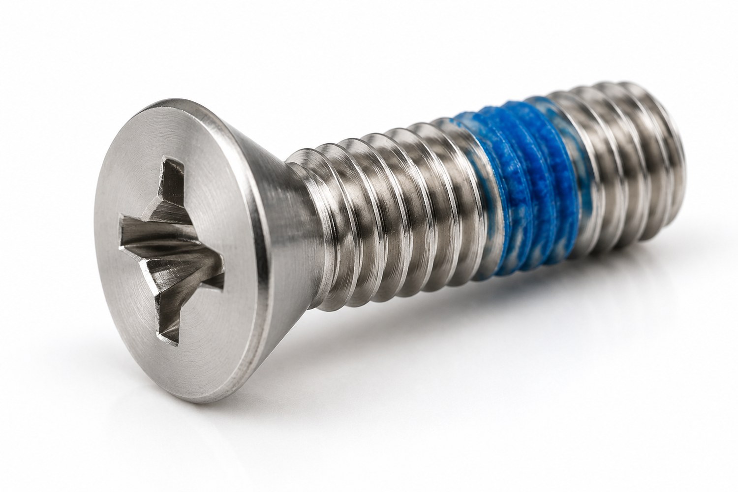
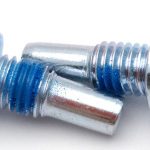
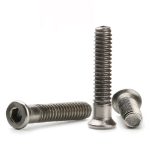
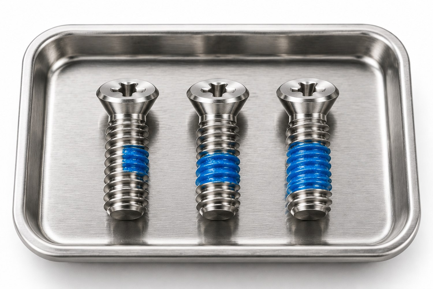
The part this page describes: countersunk head, cross recess, plain stainless surface, and a blue patch band on the middle of the thread.
The range on the size field is wide, from M1 up to M14, and it is worth saying plainly that this is not one part in fourteen sizes. Below roughly M3 the screw stops behaving like a smaller version of a bigger screw. The recess becomes a PH0 or PH1, the driver tip becomes a wear item, the patch band is only a few threads long, and the countersink depth in the plate is often thinner than the head height. That is the territory this page is written for.
A countersunk screw is chosen for one reason: nothing is allowed to stand above the surface. That is a property of the plate, not of the screw. The screw brings a cone; the plate has to bring a cone of the same angle, cut to the same depth, in material thick enough to survive the cut.
Two failures follow from getting that wrong, and they look different. Too shallow a countersink leaves the head proud, which defeats the reason the part was specified and puts the head in the way of a sliding cover, a gasket face or a lens mount. Too deep a countersink lets the head sink below the surface and removes bearing material from the plate at the same time; the joint then tightens against a thinner ring of material than the drawing assumed, and a thin plate can dish around the hole before the screw ever reaches its seating torque.
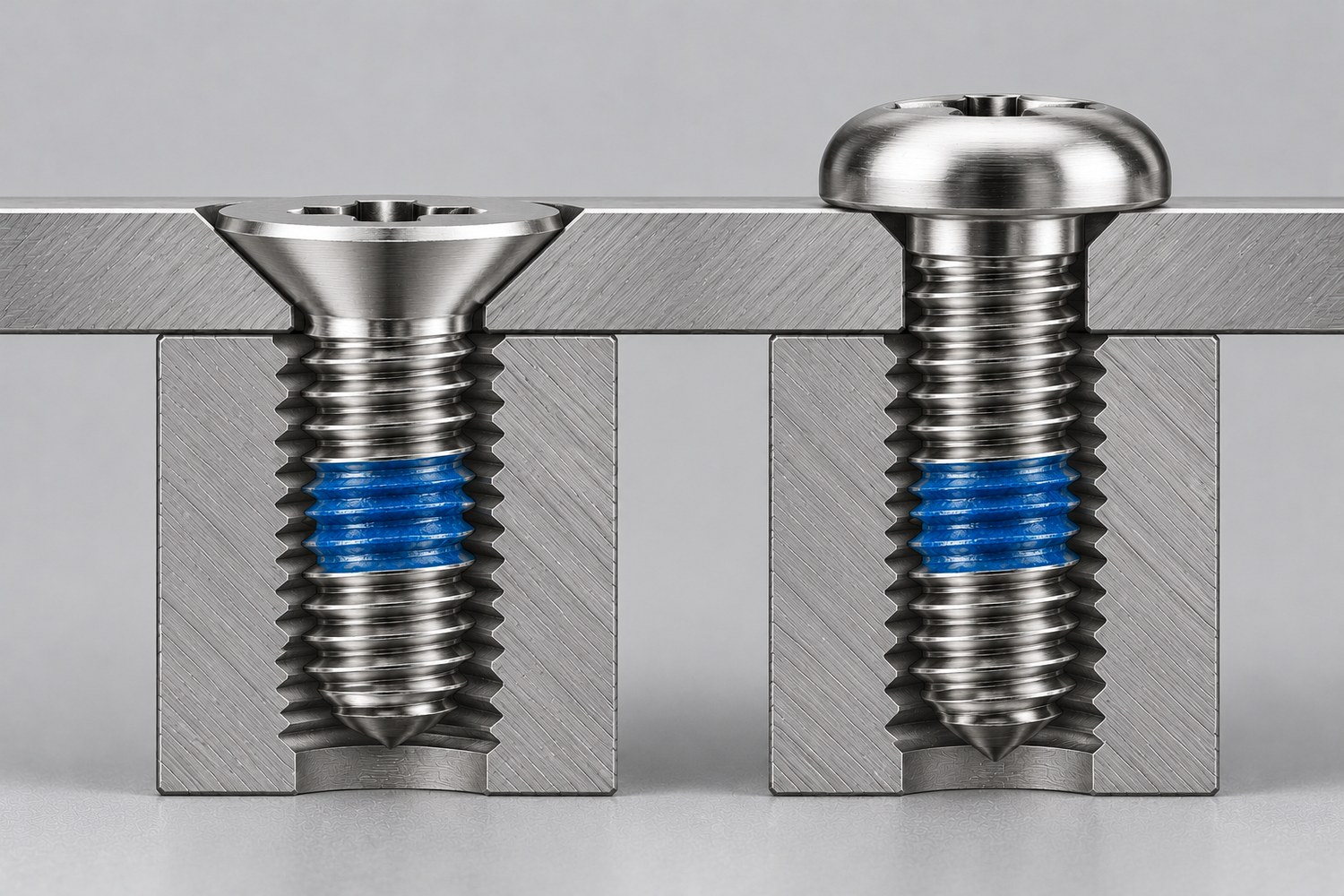
Left: the countersunk head closes the surface. Right: the same plate with a pan head, where the head height becomes an obstruction the drawing has to allow for.
So the useful information at inquiry is not only the screw size. It is the plate thickness, the countersink angle, the countersink diameter and whether the head has to finish exactly flush or is allowed to sit a few hundredths below. Give us those and the head geometry can be checked against the plate before a sample is made, rather than after the first assembly jams.
The included angle of the head is the one dimension that cannot be absorbed by tolerance. Ninety degrees is the common metric angle for this head form; eighty-two degrees appears on inch-series drawings and on parts copied from them. Put a 90 degree head into an 82 degree countersink and the two cones touch on a narrow ring instead of over the full face.
The joint still tightens, which is what makes the mistake survive inspection. What changes is where the load sits: a line contact ring at the top of the cone carries the preload in a very small area, the plate yields locally, and the screw loses clamp load without ever turning. On a part that is also carrying a locking patch, the patch hides the symptom – the screw does not back out – so the joint is discovered loose only when the assembly is opened.
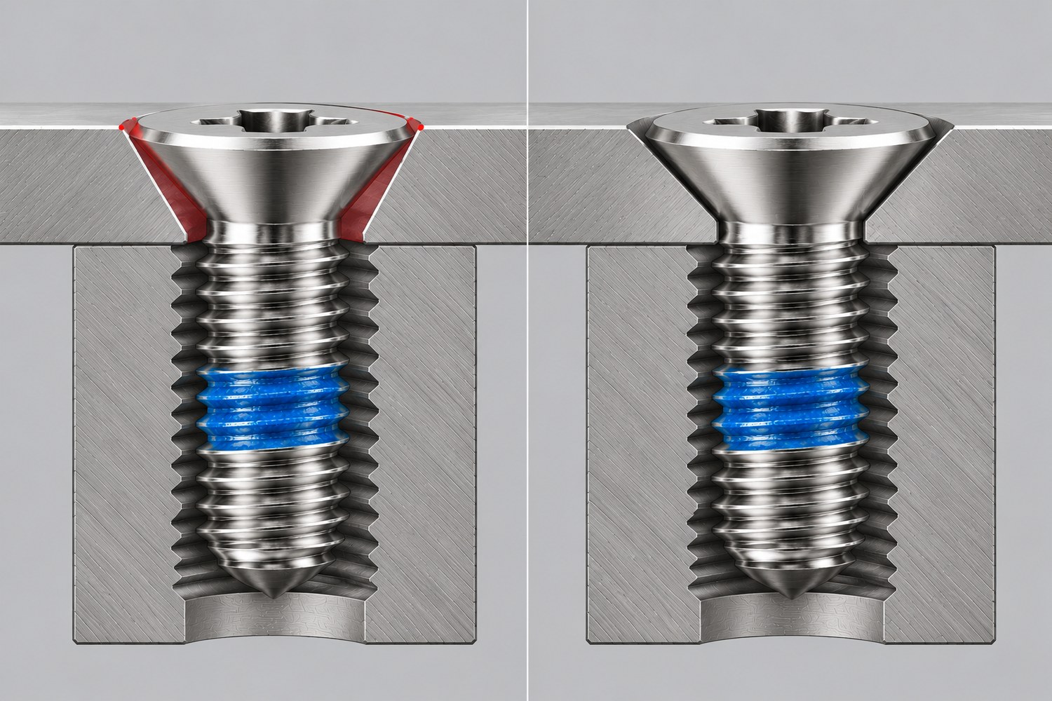
The red areas mark where the two cones fail to meet. A matched angle carries the preload across the whole seating face; a mismatched one carries it on a ring.
This is a plate-side dimension, so the check belongs on the plate drawing. When a customer sends only the screw drawing, the angle is confirmed from the mating part before tooling is released, because the head cone is cut into the die and a change after the first lot means a new die.
On a cross recess, the driver pushes in and turns at the same time, and the geometry is designed to cam out once the torque exceeds what the recess can transmit. On a large screw that is a useful safety behaviour. On a M1.5 screw with a PH0 recess it is the failure mode: the head is a fraction of a millimetre deep, the driver tip is smaller than the point of a pencil, and a worn bit rounds the recess long before the thread strips.
Three things decide whether the recess survives production. The recess size has to match the bit size, which means the drawing should name PH0, PH1 or PH2 rather than “cross recess”. The bit has to be treated as tooling, not as a consumable that is used until it slips. And the driver has to be held on axis with enough axial load: a hand driver at an angle, or an impact driver on a micro screw, converts torque into cam-out and chews the recess.
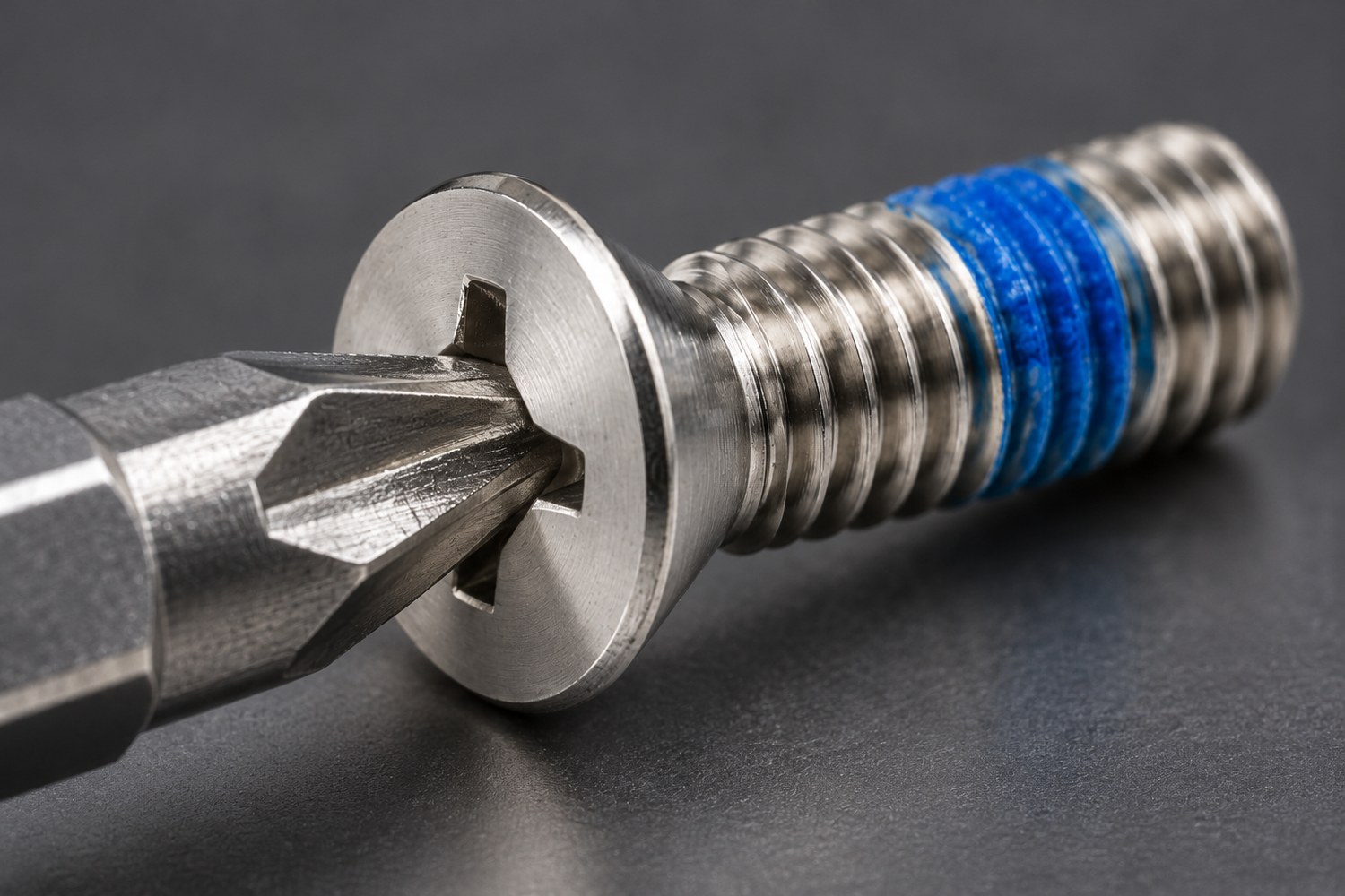
Contact happens on the four walls of the recess, not on the bottom. A bit that is undersized or worn touches only the upper corner and starts to polish the recess.
On the production side the recess is formed in the heading die, so its depth is tied to head height. A drawing that asks for a deeper recess than the head thickness allows will either thin the head under the recess or push the recess through into the shank; the first is a strength problem, the second is a scrap problem. Where a customer needs more torque capacity than a cross recess can give at that size, the honest answer is a different drive – a Torx or hex socket recess on the same head – rather than a deeper cross.
The patch is a pre-applied locking material cured onto the thread before packing. In the photographs on this page the blue band sits on the middle to lower part of the thread, roughly a third of the threaded length, with clean thread above it and a short run of clean thread below. That position is not decorative: it is chosen so the band lands inside the engaged thread of the nut or tapped hole.
The thread therefore has three zones, and they do different work. The clean thread under the head is the lead-in that starts the engagement and carries the first turns. The band is the interference zone that creates friction and resists vibration loosening. The clean thread at the tip is what enters a blind hole first and what protects the start of the thread from handling damage. Move the band up or down and one of those three jobs gets worse.
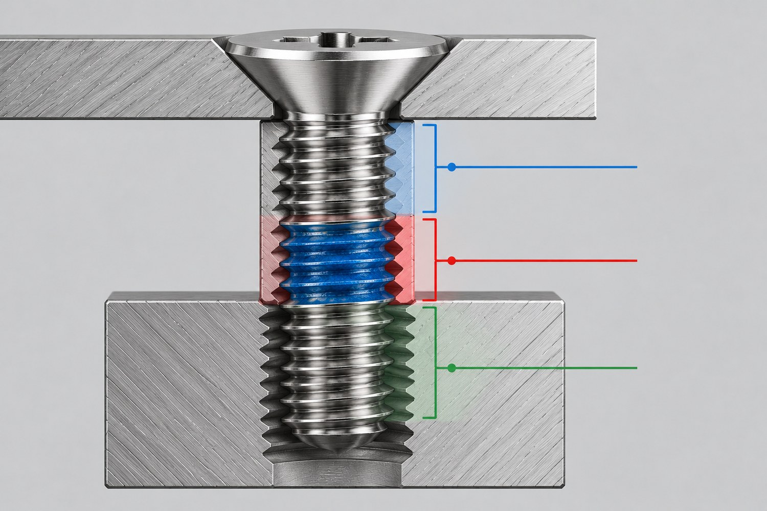
Three zones on one thread: the free lead-in, the patch band, and the engaged length. Only the band that finishes inside the engaged thread does any locking.
The practical consequence is that a screw cannot be specified by size alone. The same M3 screw with the band in the same place behaves differently in a 4 mm tapped hole and a 10 mm tapped hole, because the engaged length changes while the band does not. Send the tapped depth with the screw drawing and the band position can be placed against the engagement instead of against the shank.
The patch can be applied around part of the thread or the whole circumference. Ninety degrees, half a turn and a full turn are the three common coverages, and they behave differently: a full band gives the most consistent friction and the most even release, while a partial band is easier to break away on first installation and can be less consistent because the interference is not symmetrical. For chemical locking material the full turn is normally required, because the material has to cure across the whole thread to work at all.
Reuse is the second decision. A nylon-type patch is designed to be installed and removed a number of times and still hold; a chemical thread-locking material is closer to one installation, because the cured material is displaced rather than compressed on the way in. If the joint is opened for service, say so at inquiry – a serviceable joint is specified differently from a permanent one.
Partial and full coverage on the same screw: the band width is set by the application, the thread geometry underneath is unchanged.
Then there is the surface under the patch. On this page the finish is plain: the parts are cleaned and passivated in the ordinary stainless sense and nothing is plated on top. That matters for three reasons. There is no coating thickness sitting between the thread flanks, so the thread that is gauged is the thread that ships. There is no plating step, so there is no hydrogen to bake out afterwards. And there is no coating to chip or flake into an assembly that has to stay clean – which is why the patch, and not a coating, is the only thing added to the surface. Colour varies slightly from lot to lot on an unplated part, and handling marks show; that is the trade for having nothing on the thread.
Manufacturing
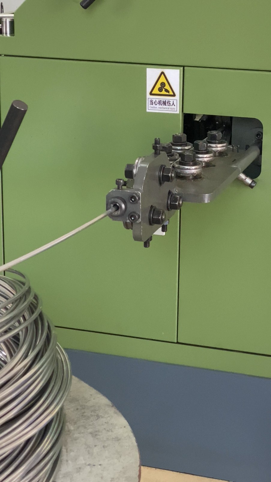
The small sizes on this page are headed in a single die: wire is cut to length, one blow forms the head and the cross recess together, and the thread is then rolled between flat dies. Nothing is machined out of the recess afterwards on a standard part, which is why the recess form is as repeatable as the die is, and why a change to the recess is a die change rather than a programming change.
The single-die route suits the small end of the range; larger diameters and shapes that need more deformation move to a two-blow or multi-station machine, where the head is formed in stages instead of one blow. The difference is not quality, it is what the geometry allows – a deep recess and a wide head in the same blow is a deformation the die has to be designed around.
|
1
Wire cut to length
|
2
Single-die heading: head and recess in one blow
|
3
Thread rolled between flat dies
|
4
Cleaned, then patch applied
|
5
Gauged, sorted, packed
|
The order of operations matters more than it looks. The patch goes on after cleaning, because a wash after application would attack the band and leave a screw that looks patched and does not lock. Thread rolling comes before the patch for the same reason: rolling a patched blank pushes the material into the die and destroys the thread form.
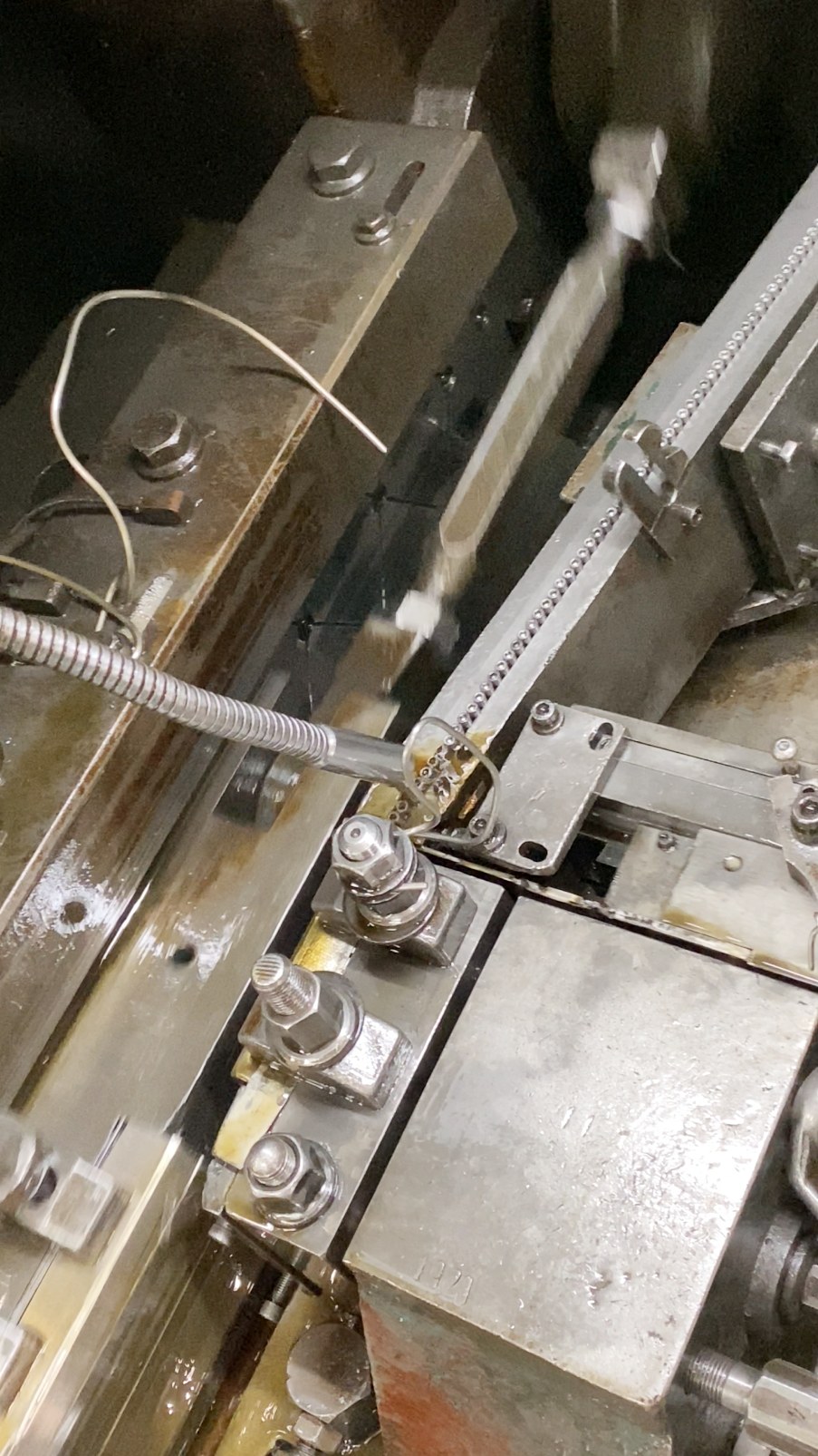
Rolled thread, not cut: the material is displaced, so the thread flanks keep a continuous grain and the minor diameter stays stronger than a machined thread of the same size.

 |
 |
Head tolerance follows the route. A cold-headed head holds about plus or minus 0.1 mm; where a drawing needs plus or minus 0.05 mm on the head diameter or the head height, that is secondary machining and is quoted as a separate operation rather than promised inside the heading step. Tooling for this part is a die set and a pair of thread rolls: standard tooling runs five to seven days, a non-standard head or recess runs ten to fifteen working days, and tooling cost is a right of use that does not ship with the parts.
Inspection
Inspection is set by the drawing and by what the part actually has to do, and the records stay with the lot. On this product the three places where a screw fails are the seating cone, the cross recess and the thread under the patch, so those are the three that get measured rather than sampled by eye.
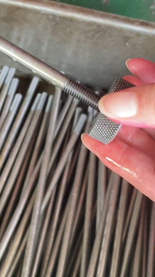
Thread gauged GO / NO-GO on the finished part |
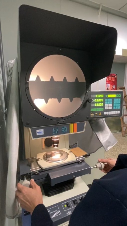
Head diameter, head height and thread length measured against the drawing |
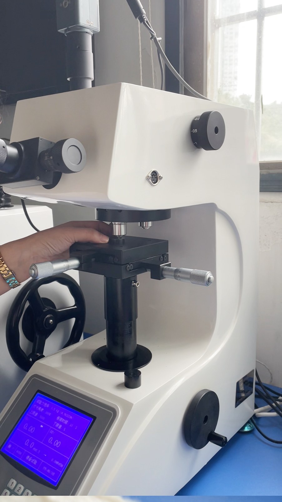
Hardness on the base metal where a property class is specified |
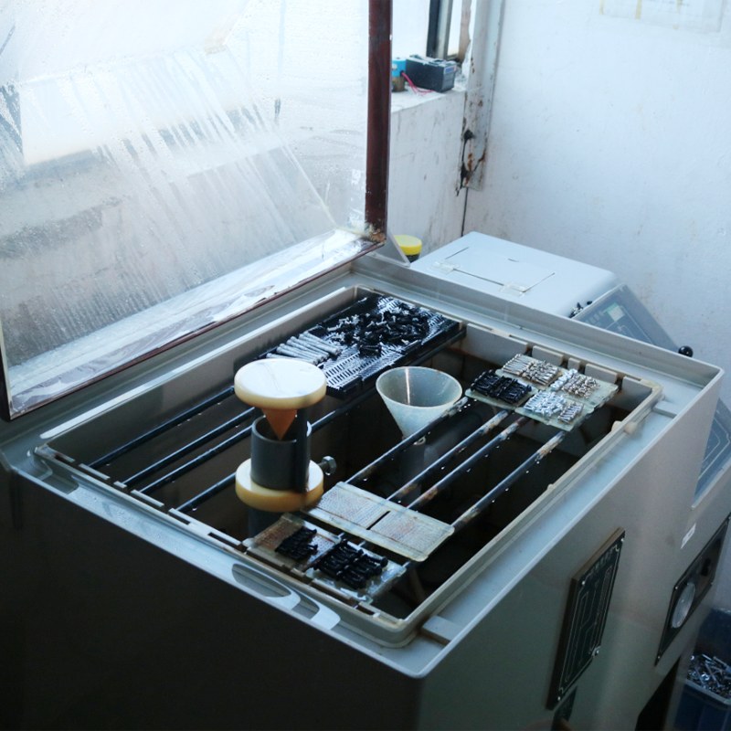
In-house salt spray where the drawing asks for a corrosion figure |
Ten or more inspection stations are used across the shop; the four shown here are the ones this product family depends on. Dimensional and thread checks are made on the finished part and reported against the drawing revision they were made to.
The patch changes how the thread is gauged, and this is worth agreeing before the first lot. The band adds material on the flank, so a NO-GO ring that was set for the bare thread will read the patch as oversize. Either the thread is gauged before the patch is applied, or the gauge condition is agreed with the patch in place; what is not acceptable is a thread that was never gauged in the condition it ships in.
Batch records cover the wire lot and material certificate, heading, thread rolling, cleaning, patch application, gauging and the visual sort. In-house salt spray results are reported as our own test record and are kept separate from third-party reports; the two are never merged into a single number, and where a project needs an external report that is agreed before the lot runs, not after it.
Certificates
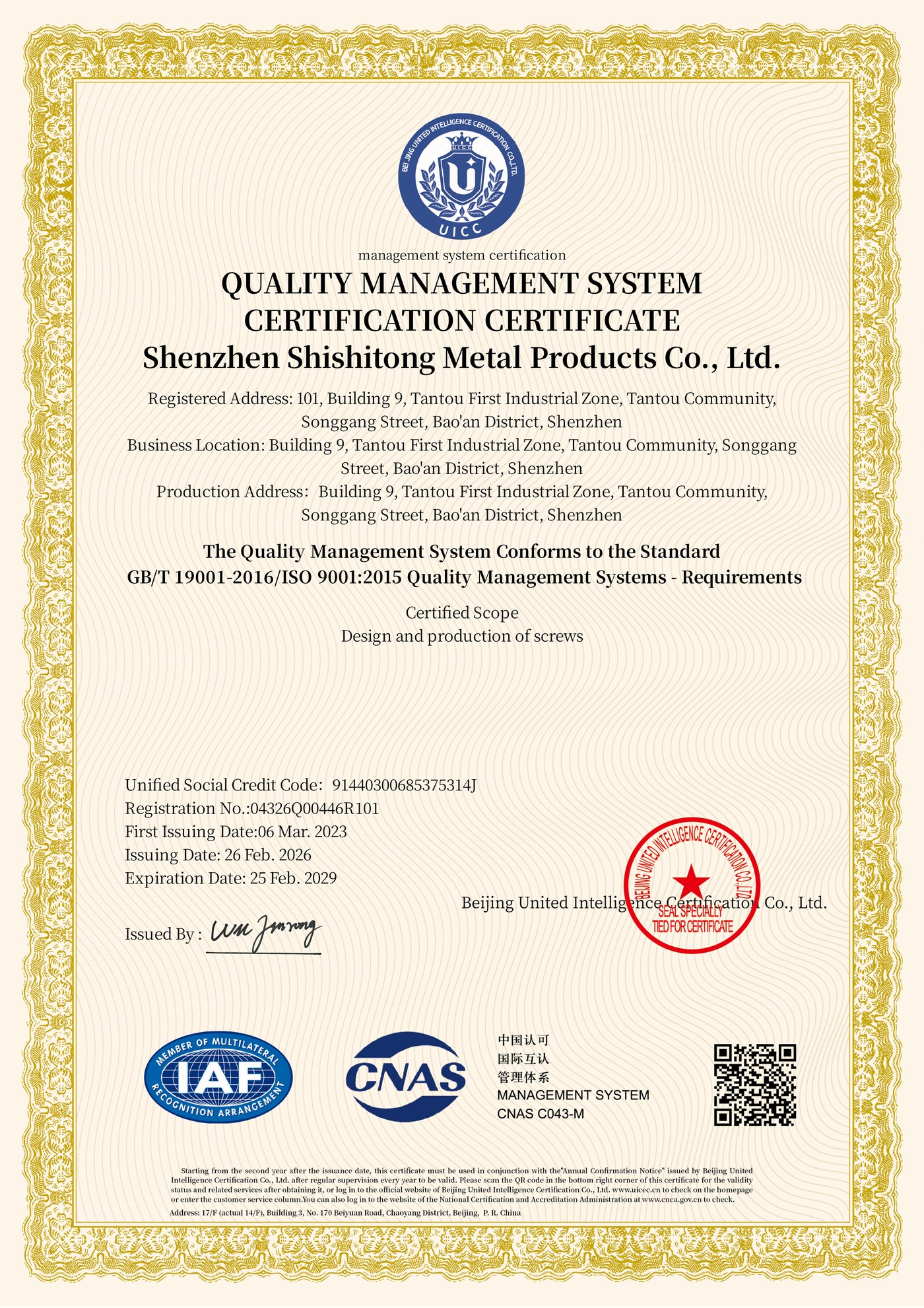
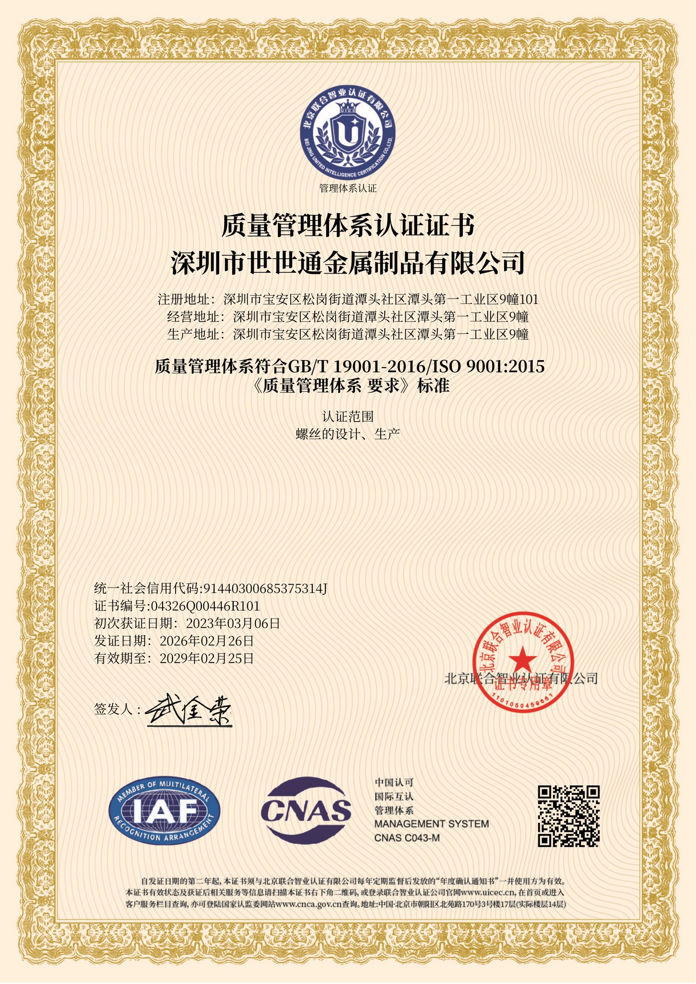
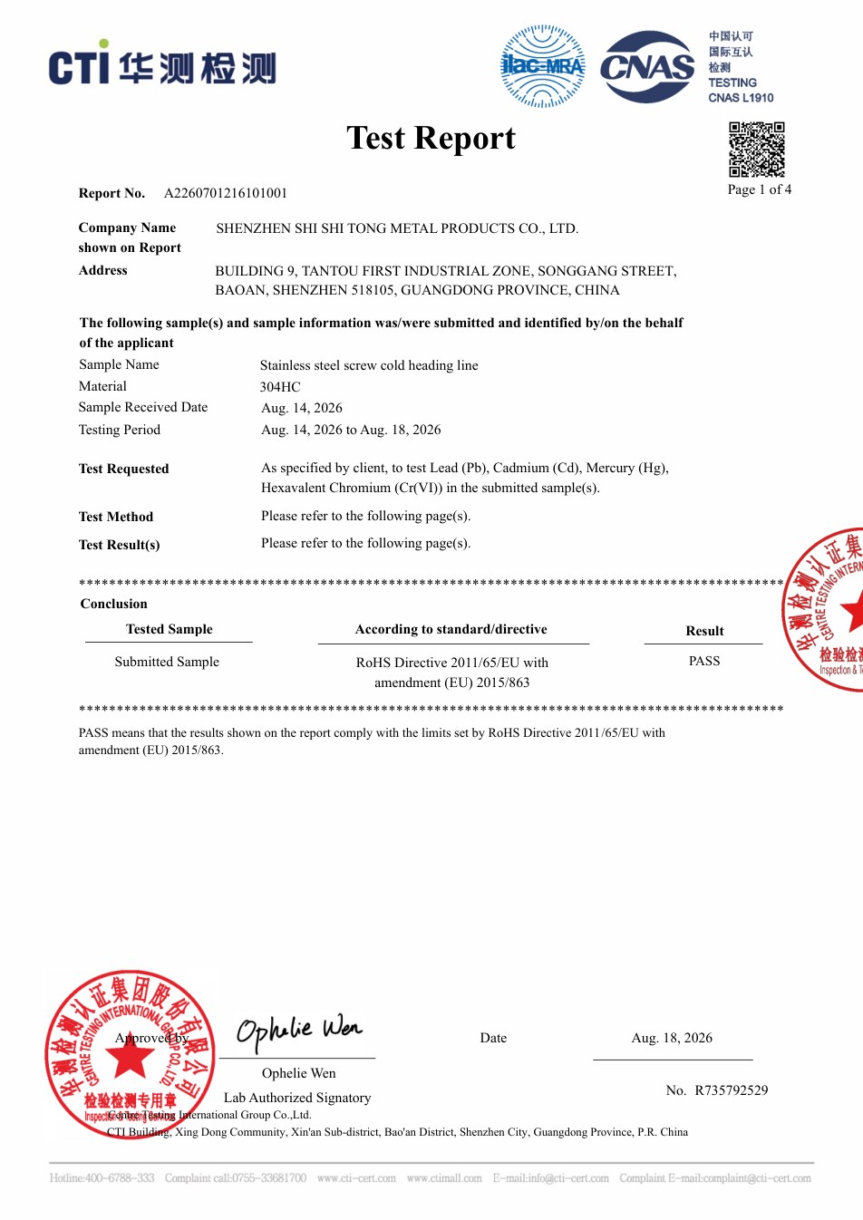
The quality management certificate, the RoHS position for stainless material and the registered trademark are the documents buyers ask for most often on this product family. Material certificates travel with the lot; test reports for a specific lot are issued with that lot.
|
ISO 9001:2015 – quality management system |
ISO 9001 – Chinese issue |
|
RoHS – stainless steel fasteners |
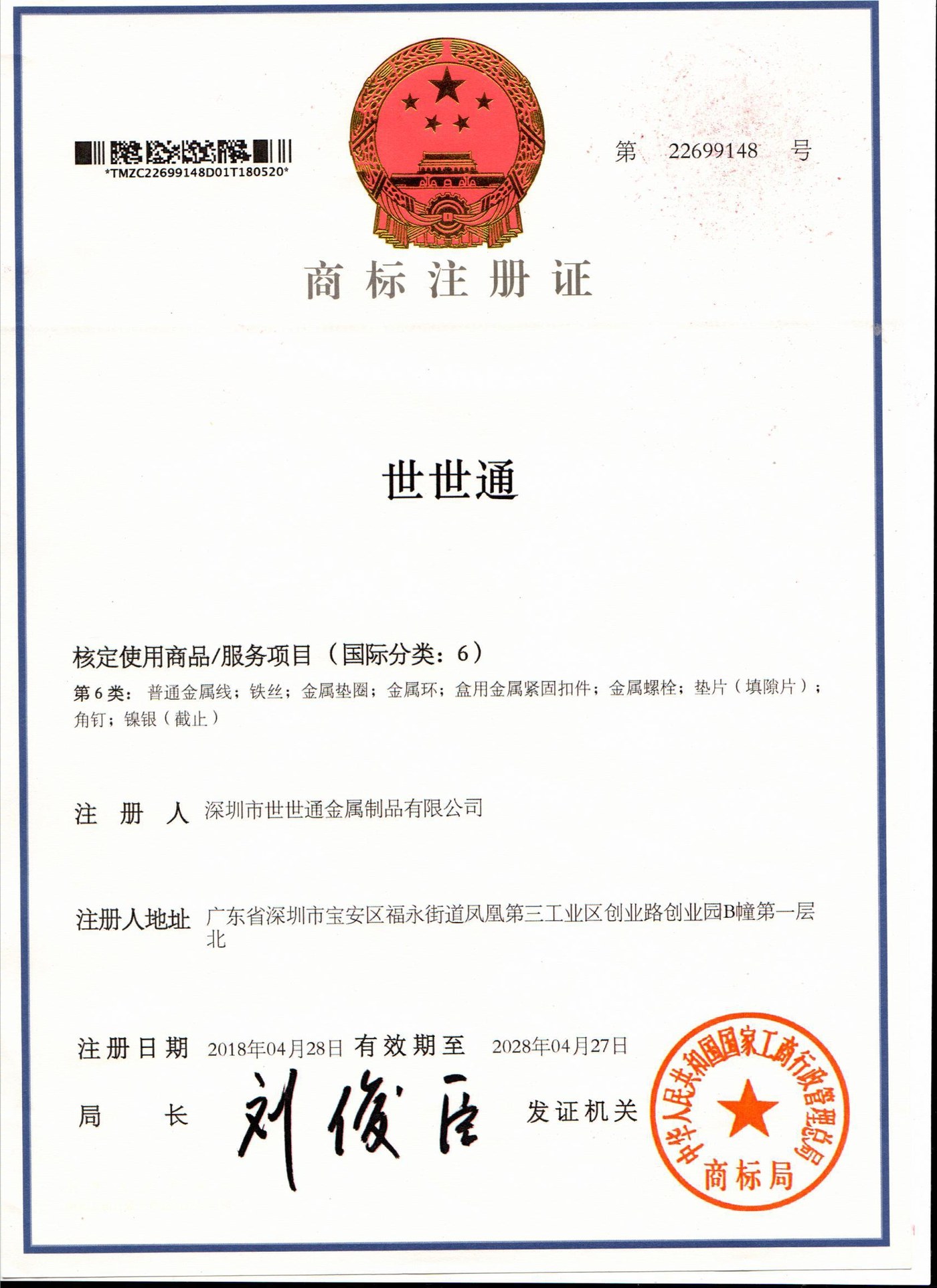
SHISHITONG registered trademark |
RoHS is stated for the material family, not as a blanket claim that every finished part has been individually tested; where a customer needs the report against a specific lot, it is named on the purchase order. If the assembly falls under a scheme we do not hold – ISO 14001 and IATF 16949 are the two that come up most often – the answer is no, and it stays no rather than being written into a quotation.
Two equipment families account for most of the enquiries on this part: machine vision and industrial sensing equipment, and laboratory and diagnostic instruments. Both need a head that closes the surface, both are opened for service, and both are assembled by hand at a bench where a dropped screw is a lost screw.
Pain point. A camera or sensor housing is a stack of machined plates around a lens axis, and every fastener in that stack is a potential source of movement. Vibration from a cooling fan, a moving axis or a conveyor reaches the housing continuously; a screw that loses a fraction of a turn changes the distance between the sensor and the object it is measuring, and the fault shows up as a drifting reading rather than as a loose screw.
Analysis. Two things have to be true at once: the head cannot stand proud into the optical path or into the space where a filter or a cover glass sits, and the joint cannot relax. A countersunk head solves the first. The second is where the patch earns its place – a pre-applied band creates interference in the engaged thread and keeps the preload from walking away, without a liquid applied at the bench that can migrate onto the lens or the sensor window.
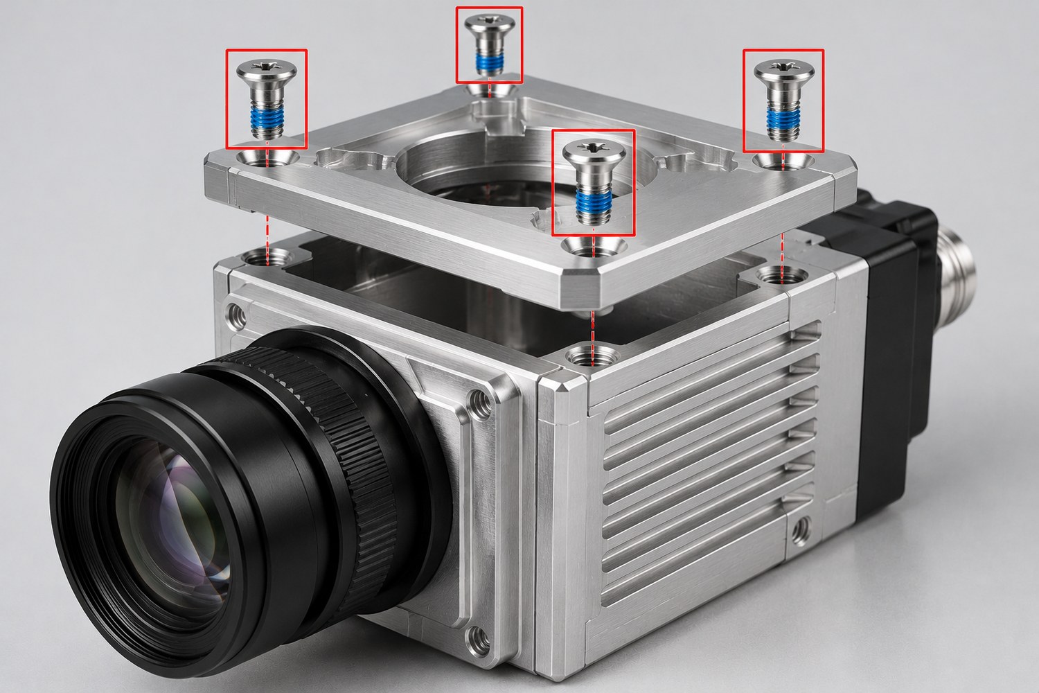
A typical stack: flange plate, body, lens mount. The highlighted screws sit below the flange face so nothing protrudes into the optical clearance.
What we control. The head cone angle and head height against the countersink in the plate; the recess size against the bit the line actually uses; the position of the patch band against the engaged thread in the tapped hole; and the thread itself by GO / NO-GO in the condition it ships in. What we do not control is the plate: if the countersink is cut shallow or at the wrong angle, the head geometry is correct and the joint is still wrong.
Pain point. Instrument panels are opened repeatedly – for calibration, for a consumable change, for cleaning – and the same screws go back in each time. A chemical locking material that was designed for one installation is the wrong choice here: it breaks down after the first few cycles, and the technician either re-applies a liquid at the bench or runs the panel without locking at all.
Analysis. The joint needs locking that survives disassembly, on a head that sits flush in a brushed stainless or painted panel so the front face stays cleanable. A nylon-type patch is the usual answer for a serviceable joint: it compresses rather than cures, so it can be re-engaged a number of times, and it does not leave a residue on the panel or on the technician’s gloves.
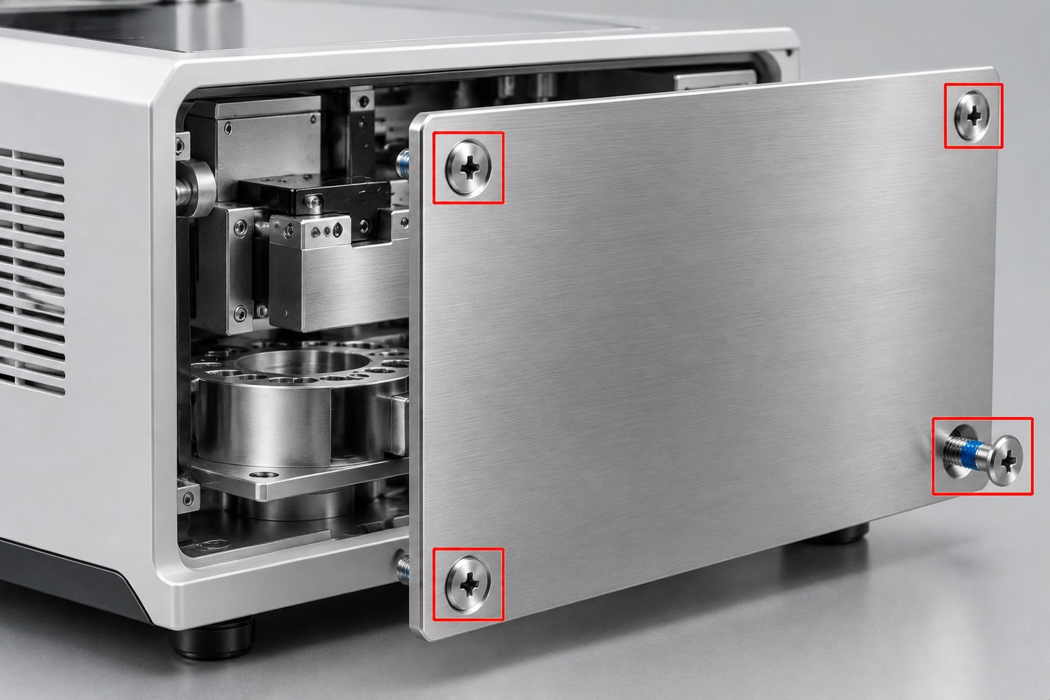
A panel that comes off for calibration: flush heads at the corners, and a patch that tolerates being taken out and put back.
What we control. The patch type and coverage are selected against the number of service cycles stated at inquiry; the head sits flush so the panel face stays flat and wipeable; and the thread is gauged so a patched screw still enters a clean tapped hole by hand for the first turns. Where the panel is thin, the countersink depth is checked against the plate thickness before the lot runs.
Engagement length is usually discussed as a strength question – how many threads are needed before the screw breaks instead of the thread stripping. On a patched screw it is also a locking question, and the two answers are not the same. A thread that is strong enough to hold the load can still have the patch band sitting in a part of the hole where nothing engages it.
A common starting point for engagement is one diameter in steel and around one and a half diameters in aluminium, confirmed against the tapped material and the thread class. The patch band then has to fall inside that length, not at the tip. In a blind hole the last turns of the screw sit in the unengaged run-out below the tapped depth: a band placed there locks nothing, and the screw behaves like a plain one while looking patched.
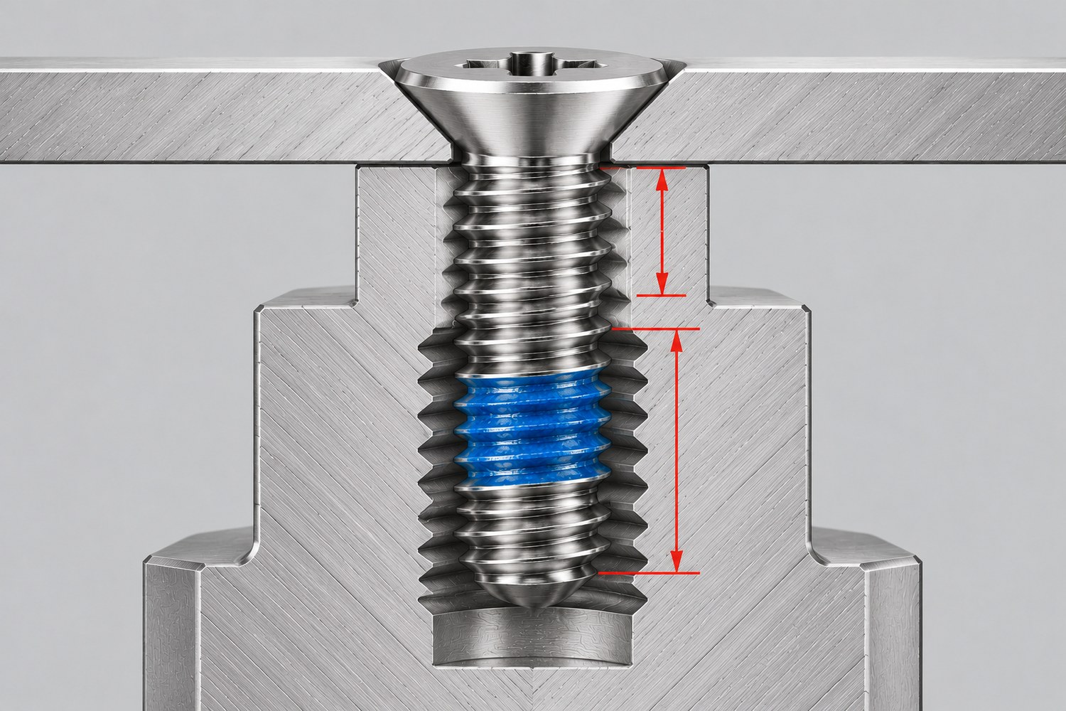
The band has to finish inside the engaged thread. Where the tapped depth is shorter than the drawing assumed, the same screw locks in one assembly and not in the other.
This is the one relationship on this page that cannot be checked from either drawing alone. The screw drawing gives the band position in millimetres from the tip; the plate drawing gives the tapped depth and the countersink. Put them together and the question has an answer: does the band fall inside the engaged length, and by how many threads. That check is done at drawing review, before tooling, and it is the reason the tapped depth is asked for even when the screw drawing looks complete.
Both descriptions apply, and neither is a specification. It is a machine screw because it threads into a tapped hole or a nut rather than forming its own thread. It is called a micro screw at the small end of the range, roughly M1 to M3, where handling and driver control dominate the assembly. The size field on this page runs from M1 to M14, so the part number and the drawing decide which one you are buying.
The page lists stainless steel; the grade is confirmed on the drawing. In practice the calls are 304 (A2) and 316 (A4). The difference shows up first in chloride-bearing or washed-down environments, where the molybdenum in 316 buys margin that 304 does not have. State the grade and the condition rather than only “stainless”, because the same drawing in two grades is two different corrosion results.
Yes – partial coverage is available, and full coverage is the more consistent option because the interference is symmetrical. Chemical locking materials generally need the full turn to work, since the material has to cure across the whole thread. The coverage is fixed with the order, not inferred from a photograph on this page.
No, and it is not meant to. The patch is applied after cleaning and before packing, and a wash after application attacks the band. If the assembled equipment goes through an aqueous wash or a solvent clean, say so at inquiry: either the patch is specified for that exposure or the locking method changes.
It depends on the patch. A nylon-type patch is designed for repeated installation and removal and still holds after a number of cycles; a chemical thread-locking material is closer to a single installation, because the cured material is displaced rather than compressed. Tell us how many times the joint will be opened and the patch type is selected against that, instead of being chosen by habit.
Yes. The countersink removes material from the plate, and on a thin sheet the remaining section under the head can be a small fraction of the nominal thickness. The check is whether the plate still has enough material to carry the preload without dishing, and whether the countersink depth can be cut without breaking through. Give us the plate thickness with the screw drawing and the two can be checked together.
Yes – Pozi, slotted, Torx and hex socket recesses are all formed in the same heading operation, and the head form stays the same. What changes is the tooling and, at the small sizes, the torque the recess can transmit. If the reason for the change is cam-out on the line, a Torx recess is the more effective answer than a deeper cross.
The pages below cover the neighbouring decisions: the same head form in other finishes, the Pozi version of the same recess family, the self-tapping version where the plate is not tapped, and the undercut head where a flush face needs a relieved corner.
| Stainless Steel Flat Head Screws
The same countersunk family in stainless, without the pre-applied patch.
|
| Black Countersunk Screws
Countersunk head with a black finish, where the joint needs a dark face rather than bare stainless.
|
| Csk Pozi Screws
The Pozi version of the same recess decision, for lines that have standardised on Pozi drivers.
|
| Csk Phillips Head Self Tapping Screw
The same head and drive where the plate is not tapped and the screw cuts its own thread.
|
| Flat Undercut Screws
A relieved head-to-shank corner, where a fillet would otherwise foul the countersink.
|
Customers
Buyers normally start with a sample card and a drawing, then come to the floor before the second order. The visit is spent on the machine that will run their part, the gauges that will judge it, and the packing that has to protect a patched thread in transit – a patch that rubs against a carton wall for a week is a patch that has to be checked on arrival.
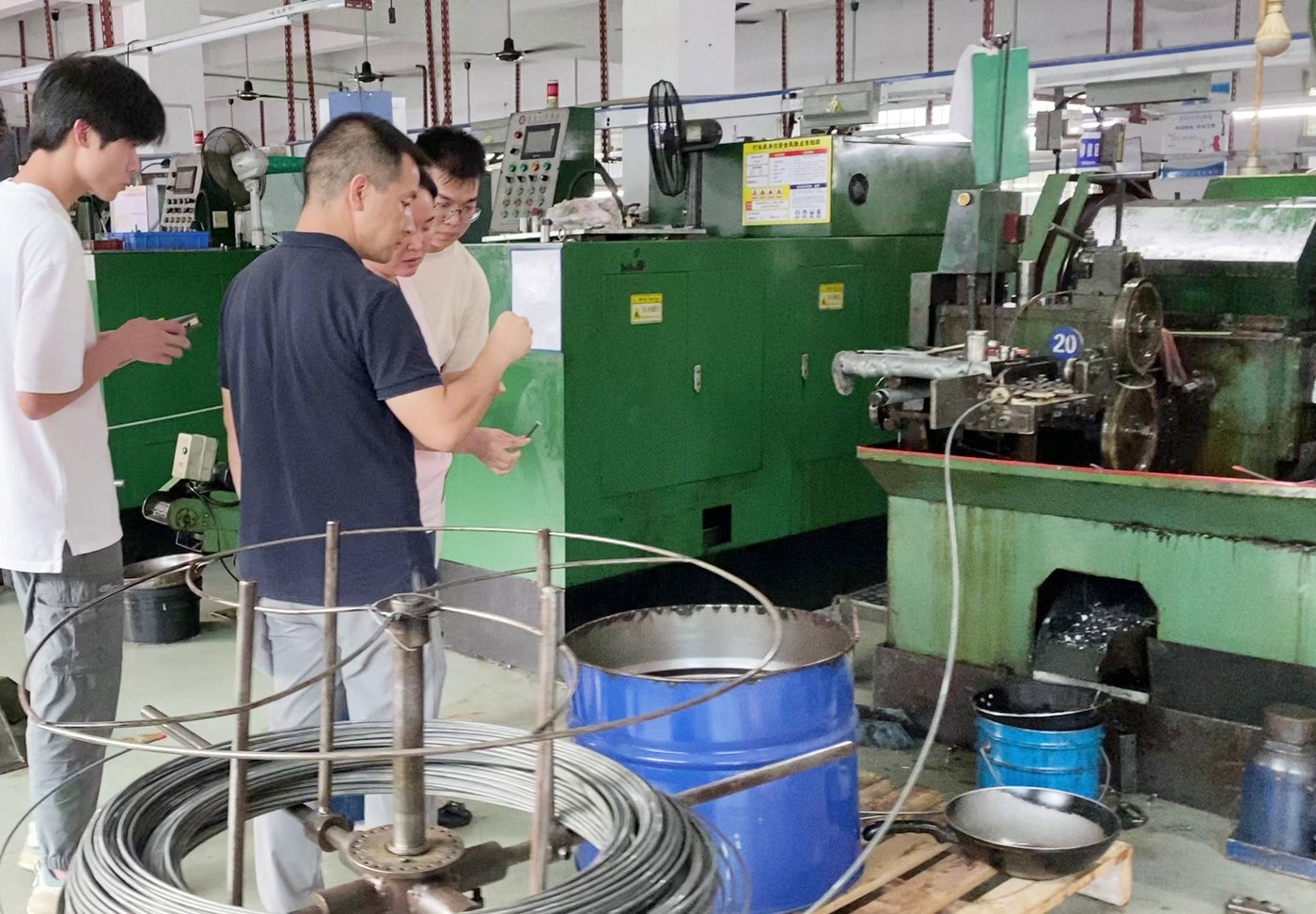
A customer visit on the floor, at the machines that run their part.
Samples are made on the same tooling as production, so what is proved on the sample is what the lot repeats. Where a drawing needs secondary machining to hold plus or minus 0.05 mm on the head, the sample is made that way too and the route is named in the quotation rather than discovered at the first production run.
Send the drawing, the grade and the tapped depth
Tell us the grade, the size and thread, the plate thickness and countersink angle, the tapped depth, how many times the joint will be opened, and the quantity per delivery. With those we can check the head against the plate and the patch band against the engagement before quoting.

 +86 13143444311
 sst@szsst88.com