
 +86 13143444311
 sst@szsst88.com
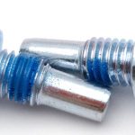
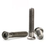

If a PVD chamber takes longer to pump down after shield or fixture maintenance, inspect the fastener interfaces that changed. A blind tapped hole can retain gas below a screw, and a restricted escape path can prolong its release. A vented titanium screw helps only when its bore connects that volume to the chamber and remains open after tightening. A slow pressure trace alone does not prove the screw is responsible.
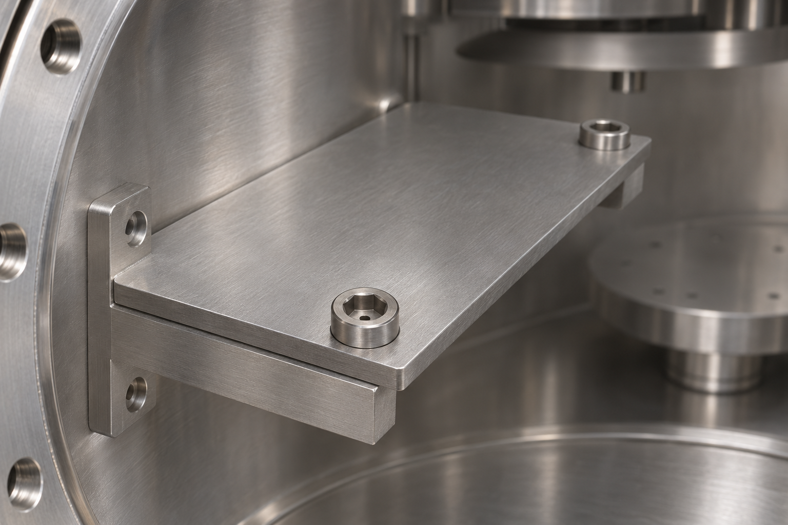
Identify what changed during maintenance
Removable shields, baffles and fixture brackets introduce several joints inside a deposition chamber. Replacing a screw with one that has the same nominal thread size does not guarantee the same venting behavior. The replacement may be solid, longer, differently recessed, or installed with a new washer. A thicker shield can also move the head outlet into an enclosed pocket.
Start with the maintenance record: identify the parts removed, screw positions changed, washer stack and drawing revisions. Compare the pressure history at the same elapsed time, chamber temperature, gauge location and pumping configuration. Keep base-pressure checks separate from pressure during deliberate process-gas flow.
Inspect internal hardware only after the equipment has been shut down, isolated, vented and made safe under the equipment manufacturer’s maintenance procedure. Do not loosen fasteners in an operating vacuum system.
Trace the complete gas path
For an axial vent, draw a continuous route from the pocket below the screw tip, through the screw bore, into the drive recess and out to the chamber. Every segment must remain open in the assembled condition. Vented hardware addresses gas trapped around fastener interfaces; the useful feature is the connected escape route, not the titanium label alone.
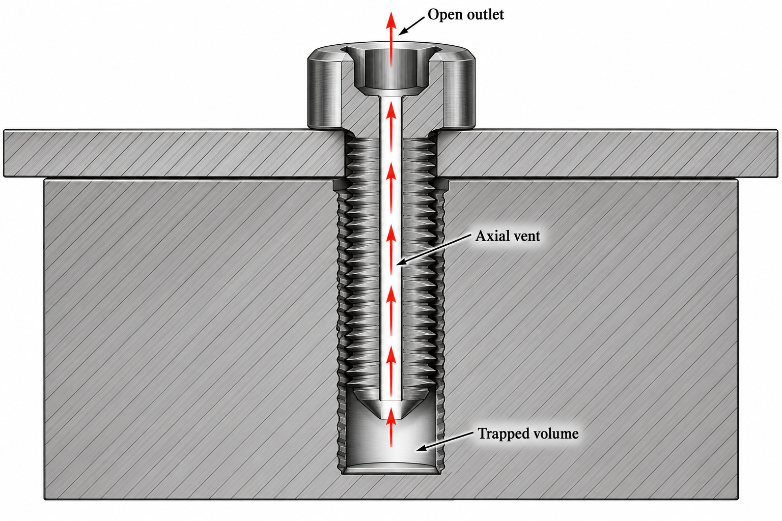
- At the tip: the bore entrance must not be sealed against the blind-hole bottom. Include the real drill-point shape and usable thread depth.
- Along the bore: diameter, length and any local restriction influence the escape path. A visible hole at one end does not establish continuity.
- At the head: a cap, cover or close-fitting counterbore can enclose the outlet. Check the assembled clearance, not just the loose screw.
- Under mating surfaces: an axial bore may vent the pocket beneath the tip without venting every pocket beneath a broad washer or panel. Those interfaces need their own route assessment.
Keep the whole path on the vacuum side. An axial hole through a pressure-boundary fastener can create a real leak if it connects the chamber to atmosphere.
Separate geometry evidence from system symptoms
| Observation | What to check | Proportionate action |
|---|---|---|
| A slower late pump-down follows shield replacement | Changed screw length, solid-for-vented substitution, added washers and covered outlets | Compare the old and new assembly sections before changing the pump or every fastener |
| The loose screw has an open bore, but the installed route is enclosed | Head pocket, cover clearance and tip-to-bottom relationship | Correct the blocked interface through an approved drawing change |
| Pressure changed without a fastener or fixture change | Equipment-side pumping, valve, gauge and leak evidence | Follow the equipment diagnostic procedure; do not infer a fastener fault |
| A replacement screw reaches torque before the shield seats | Bottoming, incomplete thread engagement or an interfering transition | Stop assembly and resolve the fit; additional torque is not a vent-path repair |
Gas released from an internal trapped volume is one possible load on the vacuum system. A virtual leak differs from an external leak: the gas is already inside an enclosed internal volume and escapes through a restricted connection. A routine external helium check does not, by itself, establish that all internal trapped volumes have been eliminated.
Estimate the pressure contribution
Near a steady operating point, an added gas load can be related to pressure by Δp ≈ ΔQ / Seff. Here ΔQ is the additional gas throughput in mbar·L/s, and Seff is the effective pumping speed at the chamber in L/s. Use chamber-side speed, not simply the pump nameplate rating. This follows the gas-load and effective-pumping-speed balance.
If the allowed added pressure is 2 × 10⁻⁷ mbar and the chamber-side speed is 50 L/s, the corresponding added gas-load budget is:
ΔQ = 50 × 2 × 10−7 = 1 × 10⁻⁵ mbar·L/s.
These selected inputs illustrate the calculation; they are not measurements or a fastener acceptance limit. The budget belongs to the combined additional gas load, not automatically to each screw.
The calculation does not predict the full pump-down curve. Pressure-dependent pumping speed, changing gas release and restrictions in the system can invalidate a constant-speed approximation. Use the model to frame the equipment team’s investigation, then evaluate the actual pressure record.
Review the joint before changing the screw
A larger bore is not a free improvement. It removes material from the screw and can reduce the remaining section at the thread root and below the drive recess. The minimum wall is also affected by bore offset and drill wander. Review tensile loading, installation torsion, engagement and bearing support together.
Do not transfer a torque setting from a solid stainless screw to a hollow TA2 screw solely because the nominal thread matches. Material condition, friction, net section and head geometry differ. The screw still has to clamp the shield without bottoming, stripping or damaging the receiving thread.
For custom titanium screws, specify the purchasing standard and material condition alongside the bore and external geometry. A TA2 designation should not be substituted for an overseas grade without confirming the applicable material requirements.
Define drawing and acceptance requirements
A useful drawing package includes the screw and the mating assembly. Mark the bearing face, overall length, full-thread interval, bore diameter, bore position relative to an agreed datum, minimum remaining wall and required outlet clearance. Show the bottom of the receiving hole rather than ending the drawing at the last visible thread.
- Confirm the component geometry and the actual final-state thread fit.
- Verify bore continuity with an agreed method that is suitable for the hole size and length.
- Inspect the assembled outlet and tip clearance at the limiting tolerance conditions.
- Approve the installation method and joint-load requirement before the equipment comparison.
- Record the drawing revision, material lot and fastener positions used in the comparison.
Dimensional acceptance and an open bore establish component facts. The equipment owner still verifies chamber performance using the agreed system procedure. Our custom screw engineering and manufacturing review connects the requested geometry with a feasible process and inspection plan.
Technical FAQ
Can vented screws fix every slow PVD pump-down?
No. They address a connected trapped volume at a fastener interface. A pressure change can have other equipment-side causes, so confirm the changed assembly and the gas path before attributing the problem to screws.
Does titanium itself provide the venting function?
No. Venting comes from the hole or other designed passage. Titanium selection is a separate decision involving the material standard, service conditions and joint requirements.
Why can an open bore still fail to vent the assembly?
The screw tip may close against the hole bottom, or the head outlet may be enclosed by a cover or counterbore. Inspect the complete assembled route rather than the loose screw alone.
Can a larger vent hole be specified to speed evacuation?
Only after reviewing both the flow restriction and the remaining load-carrying section. The bore must fit within the strength, wall-thickness, drive and manufacturing constraints of the same screw.
Which information should accompany a drawing review?
Include the screw drawing, mating-hole section, vacuum-side location, permitted material specification, installation requirements, quantity and measurable acceptance criteria.
Review the screw and the mating assembly together
Send your screw drawing, a section through the mating hole, material specification, quantity and critical acceptance requirements. Shi Shi Tong reviews the geometry, manufacturing route and inspection requirements before confirming a custom screw proposal.
Copy this email address and attach your drawings in your email service:sst@szsst88.comOpen Email App →
If your email app does not open, copy this address into your email service.