Tel:
+86 13143444311
Email:sst@szsst88.com
Fax:+0086-755-27322278
Address:Building 9, First Industrial Zone, Tantou Industrial City, Songgang Street, Baoan District, Shenzhen 518105, Guangdong, China
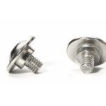
Type:Low Profile Socket Head Cap Screw Dimensions
Materials:Stainless Steel
Surface treatment:Plain
Head Type:Low profile socket cap
Drive:Hexagon socket (Allen)
Thread:Machine thread
Point:Plain, chamfered
Forming:Single Die Heading
Size:M1 M2 M3 M4 M5 M6 M7 M8 M9 M10
A low profile socket head cap screw is defined by four dimensions: head diameter, head height, socket across-flats and socket depth. We make them in stainless steel from M1 to M10 and quote against a drawing that states those four numbers and the datum for each.
Watch the factory video·Email sst@szsst88.com
ISO 9001:2015 · Manufacturing since 1998 · 8,678+ customers · 89 countries and regions
Made to order – there is no stock catalogue. Each part is produced to your drawing, and production starts after drawing review and first-article approval.
The dimensions of a low profile socket head cap screw are four numbers: head diameter, head height, socket across-flats and socket depth, plus the thread and the overall length. The part recorded here is stainless, plain, quoted from M1 to M10.
Head diameter. Measured across the cylindrical head, at the widest point.
Head height. Measured from the bearing face to the top face, not across the whole part.
Socket across-flats. The key size the hexagon accepts, measured between opposite flats.
Socket depth. Measured from the socket floor to the top face, with the key that will drive it.
A dimensions page for the low profile socket head cap screw exists because these four numbers are where replacement parts fail. A screw can match on thread and length and still foul a cover, round its socket or seat on the wrong surface, and none of those failures is visible in the part number.
Head height is the number most often quoted and most often measured wrongly. It runs from the bearing face to the top face, and on a low head that distance is small; a measurement taken over the fillet or across the chamfer reads long, and a part that is correct can then be rejected while a part that is too tall is accepted.
Head diameter is measured at the widest point of the cylinder. On a low profile part the head is not tapered in the same way as a button head, so the widest point is easy to define and easy to reproduce; the number is there to make sure the head clears the pocket it sits in.
Socket across-flats is the key size, and it is measured between opposite flats rather than across corners. It is the dimension that decides whether the part can be driven, and it is the one that a worn broaching punch changes first, because the punch wears at the corners and pulls the flats in.
Socket depth is the fourth number and the one that is rarely on a catalogue drawing. It is measured from the floor to the top face, and it exists so the key can reach the floor: on a low head a key that only enters part of the way bears on a shorter length of each flat, and the load per unit area rises.
Length completes the set and is measured over the head. Where a screw passes through a plate into a pocket, the usable length is the overall length minus the plate and minus whatever stands proud, and at low head heights that arithmetic is what decides whether the joint closes.
The table below is the frame we work to for the recorded range. Exact values come from the drawing and the standard named on it; what matters here is which dimensions are controlled and how they are read.
| Size | Head diameter | Head height | Socket across-flats | Socket depth |
|---|---|---|---|---|
| M2 | Reduced, per drawing | Low, per drawing | Smallest key in the range | Bounded by head height |
| M3 | Reduced, per drawing | Low, per drawing | Key to match the socket | Bounded by head height |
| M4 | Reduced, per drawing | Low, per drawing | Key to match the socket | Bounded by head height |
| M5 | Reduced, per drawing | Low, per drawing | Key to match the socket | Bounded by head height |
| M6 and above | Reduced, per drawing | Low, per drawing | Key to match the socket | Bounded by head height |
The pattern across sizes is that head height falls faster than head diameter. Going down a size, the socket has to stay usable with a key that exists, so the head cannot simply be scaled: the wall thickness around the hexagon becomes the limiting figure, and the head height has to be kept just deep enough.
That is why the dimensions of a low profile socket head cap screw are useful when choosing a part. A size that looks generous in diameter can still have a socket too shallow for the key in the toolbox, and a size that looks small can have a deeper socket than a larger neighbour if the design allows it.
Length tolerance is quoted separately from the head dimensions, because it does not depend on them. It is set by the joint rather than by the head form.
Each of the four numbers answers a different question in the assembly, and a mistake in any one of them produces a different failure:
| Dimension | What it decides | What goes wrong if it is wrong |
|---|---|---|
| Head diameter | Whether the head clears the pocket | Binding or fouling a cover |
| Head height | Whether the assembly closes | The part stands proud or bottoms out |
| Socket across-flats | Whether the key fits | The key does not enter |
| Socket depth | Whether the key reaches the floor | The socket rounds under torque |
| Overall length | Whether the joint seats | The screw bottoms out or leaves a gap |
Read together, they explain why replacement parts for a low profile socket head cap screw are difficult. A buyer measures the old screw with calipers, matches the thread and the length, and assumes the rest; the head height and socket depth are the two numbers that a caliper in the hand does not capture well, and they are the two that decide whether the part drives.
For a supplier the practical consequence on a low profile socket head cap screw is that the drawing has to state all four, and the first article has to be measured on a projector rather than with a caliper. A dimensions page is only useful if the numbers can be reproduced.
The recorded finish is plain stainless. On a dimensions page the finish matters because it is one of the few things that does not change the numbers: there is no coating inside the socket to alter the key fit, and no plated layer on the bearing face to change the head height.
| Option | How it protects | Effect on the measured dimensions | Typical use |
|---|---|---|---|
| Passivated, plain | Removes free iron; rebuilds oxide | None measurable | Default for stainless |
| Electropolished | Levels the surface | Micrometres; socket edges rounded | Food and medical equipment |
| Black oxide on stainless | Colours the surface | Negligible | Dark assemblies |
| Nickel plated | Hard bright barrier | Measurable in the socket; re-gauge | Where a bright finish is wanted |
| Zinc plated steel | Sacrificial zinc | Measurable on head and socket | Where stainless is not needed |
That distinction is worth stating because it explains a common complaint: a plated part of the same drawing can feel different in the socket from a plain one, and it is not a tolerance error. The coating is inside the dimension, and the dimension has to be re-measured after plating.
Plain stainless has the simplest relationship between what is measured and what is used, which is why a dimensions page is usually written around it.
Three settings where the numbers decide whether the part works:
| Where it sits | A low head part is bought to replace an existing fixing where the assembly cannot change. |
| When it goes wrong | The thread and length match and the head height does not, so the cover will not close. |
| Why it happens | The original is measured with calipers and the two hidden dimensions are missed. |
| What we control | All four dimensions measured on a projector; first article fitted in the assembly. |
| Where it sits | A new assembly is laid out around a low head where the height budget is fixed by the parts around it. |
| When it goes wrong | The design assumes a head height that the chosen size cannot deliver with a usable socket. |
| Why it happens | The clearance is set by a moving part, and the fixing is at the limit. |
| What we control | Head height and socket depth checked in review; first article fitted. |
| Where it sits | A batch is checked against a drawing where the head dimensions are the acceptance criteria. |
| When it goes wrong | The measurement is taken over the fillet and the batch is judged on the wrong number. |
| Why it happens | The part is small, the datum is not obvious, and the inspector is under time pressure. |
| What we control | Datum defined in the inspection plan; measured on a projector, not a caliper. |
Four reasons that matter on a page about measurement, each tied to something the drawing or the first article has to prove:
|
Datums written with the dimensions
Each dimension is stated with the datum it is measured from, because a head height read from the wrong face is a rejection of a good part or an acceptance of a bad one. Basis: Every dimension has a datum. |
Formed, broached, threaded, passivated
The head and socket are formed and broached to the drawing, and the parts passivated so nothing is added to the measured dimensions. Basis: No coating in the numbers. |
|
Measured on the projector
The four head and socket dimensions are measured on the projector on every first article, because a caliper does not capture a socket depth reliably at these sizes. Basis: Projector, not caliper. |
Same numbers across batches
The heading punch and the broaching depth are recorded with the drawing revision, so a repeat order measures the same as the sample. Basis: Same numbers across orders. |
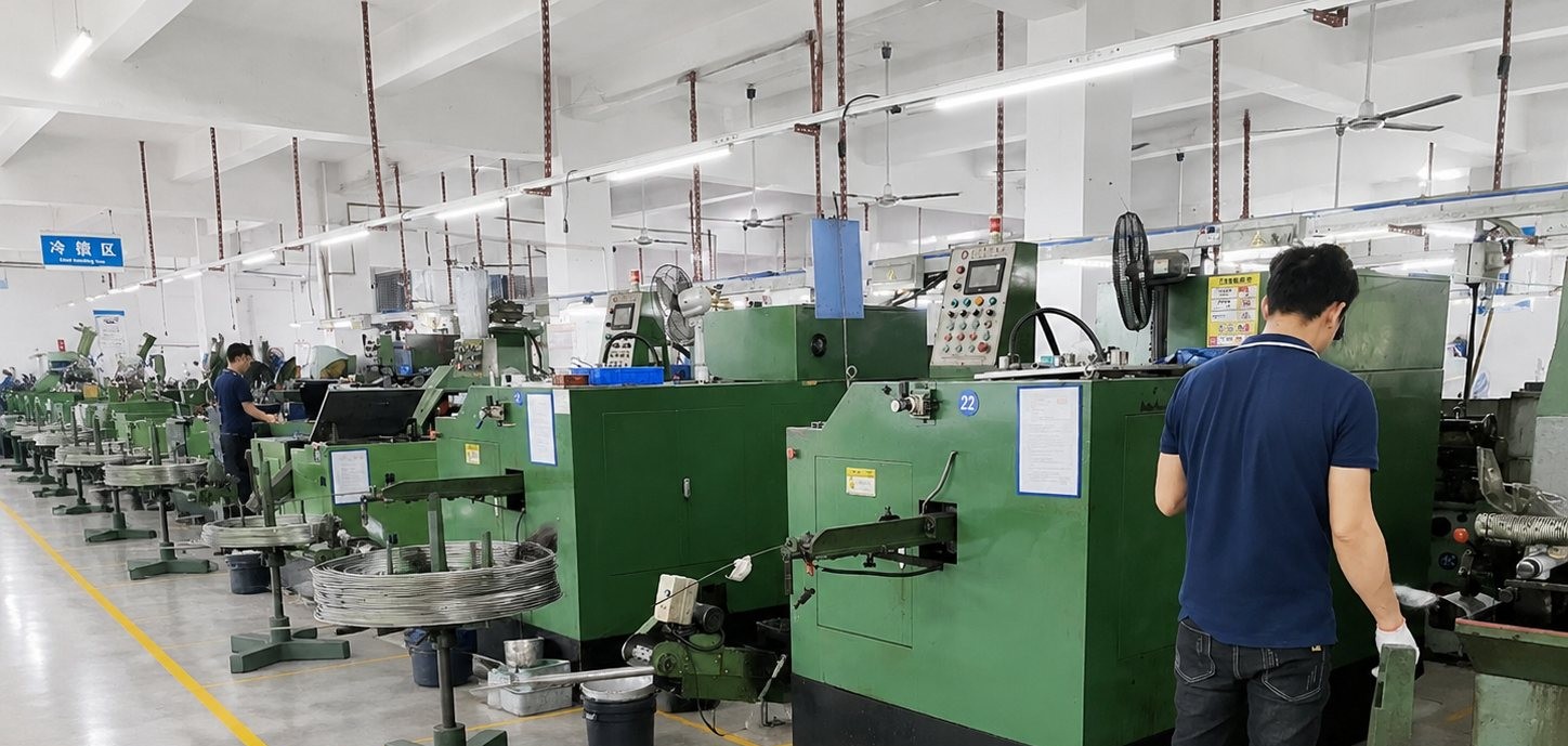
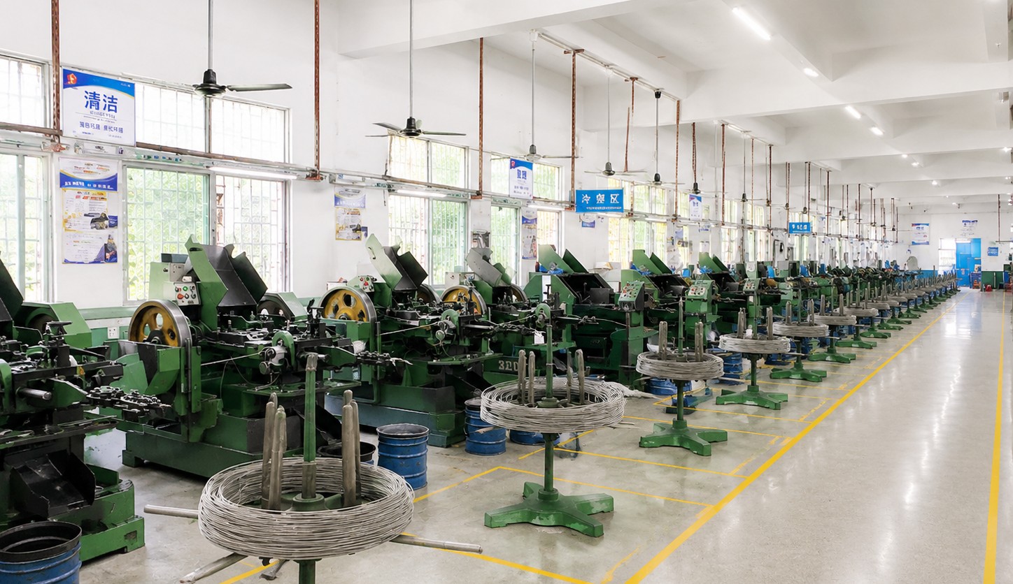
The four dimensions come out of two operations. Head diameter and head height come from the heading stroke; socket across-flats and socket depth come from the broaching punch. The thread and the length follow from rolling and from the blank length. Between them, those operations decide every number on this page.
|
|
Setting the heading stroke decides the head height, and it is where a low profile part is most sensitive. The punch stops short of a standard head, so the metal that would have formed a taller head stays in the diameter; set slightly too shallow and the head grows taller, set slightly too deep and the top becomes too thin to hold the socket.
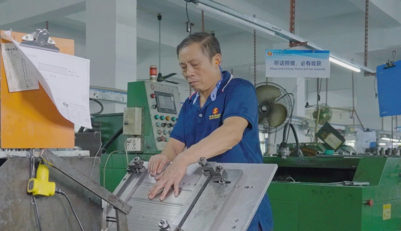
The broaching punch then cuts the socket into whatever height the head produced. This is why the two operations are measured together: a head that came out a little low with a socket cut to nominal depth has less floor under the socket than the drawing intends, and the dimension that suffers is the one nobody measures until the part rounds.
Measurement is part of the process rather than an afterthought. The first article is checked on the projector for all four numbers, and the check is repeated after any tool change, because a change in the punch or the die moves all of them at once.
What decides whether a batch matches the dimensions is how the four numbers are measured, and on what datum. The inspection plan states the datum for each; the projector does the rest.
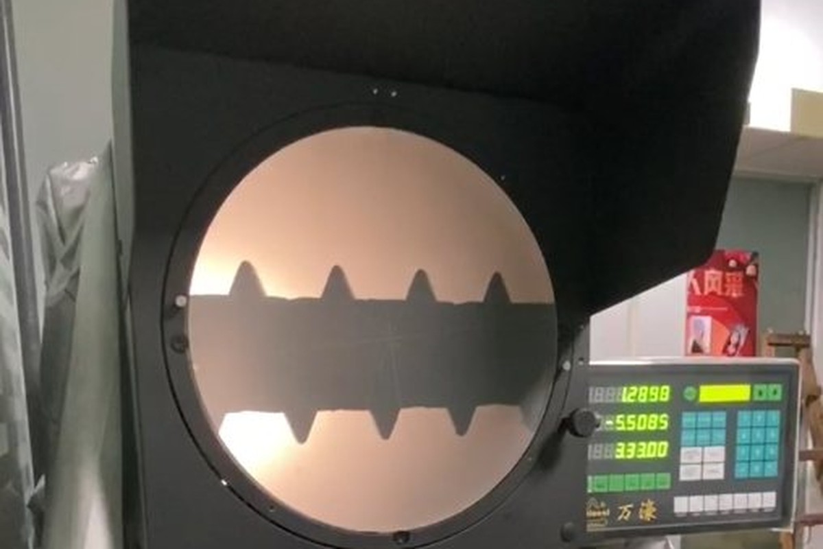
All four dimensions on the projector |
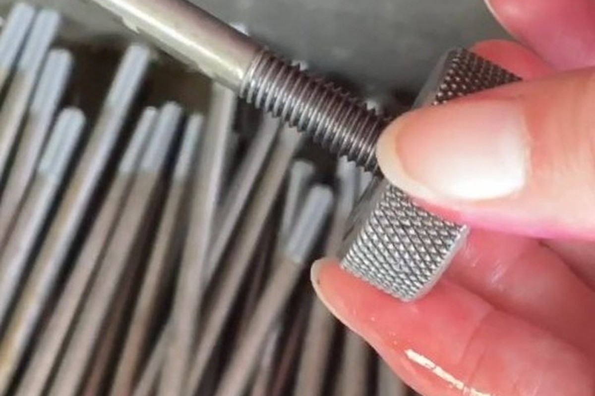
Thread and start checked |
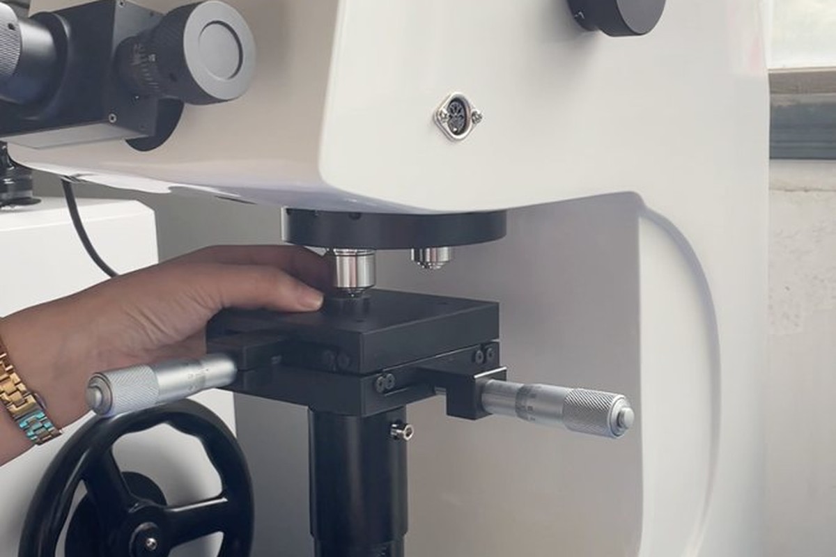
Hardness against the stainless spec |
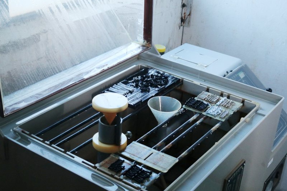
Salt-spray testing of the plain surface |
Head diameter and height are measured against the bearing face as datum; socket across-flats between opposite flats; socket depth from the socket floor to the top face. Each of those is written on the inspection plan, because the same part measured from a different datum gives a different answer.
The functional confirmation is the key. A sample from each batch is driven with the production key and the engagement is checked, since a socket depth that measures correctly can still be unusable if the floor is uneven or the corners are torn.
Length is measured over the head as well, and the batch is checked for a single length. Mixed lengths in a bin are the defect that a dimensional page cannot prevent and an inspection plan can.
Every batch is traceable to the heat of stainless it was made from. The grade and heat number appear on the material certificate supplied with the parts, and the inspection records carry the measured values for the four dimensions rather than a pass mark alone.
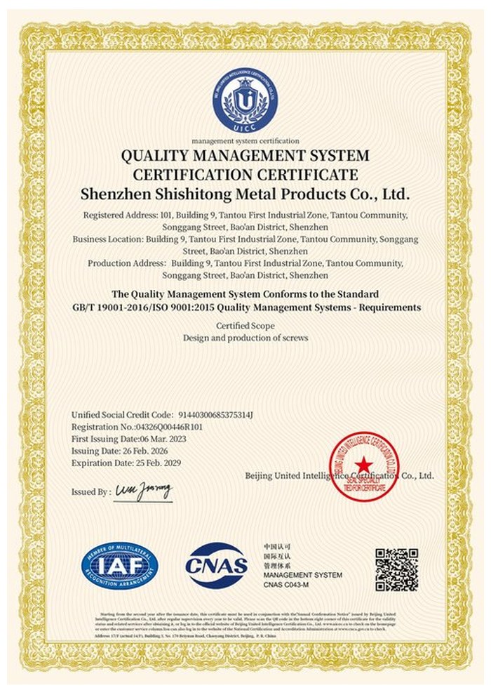
ISO 9001:2015 |
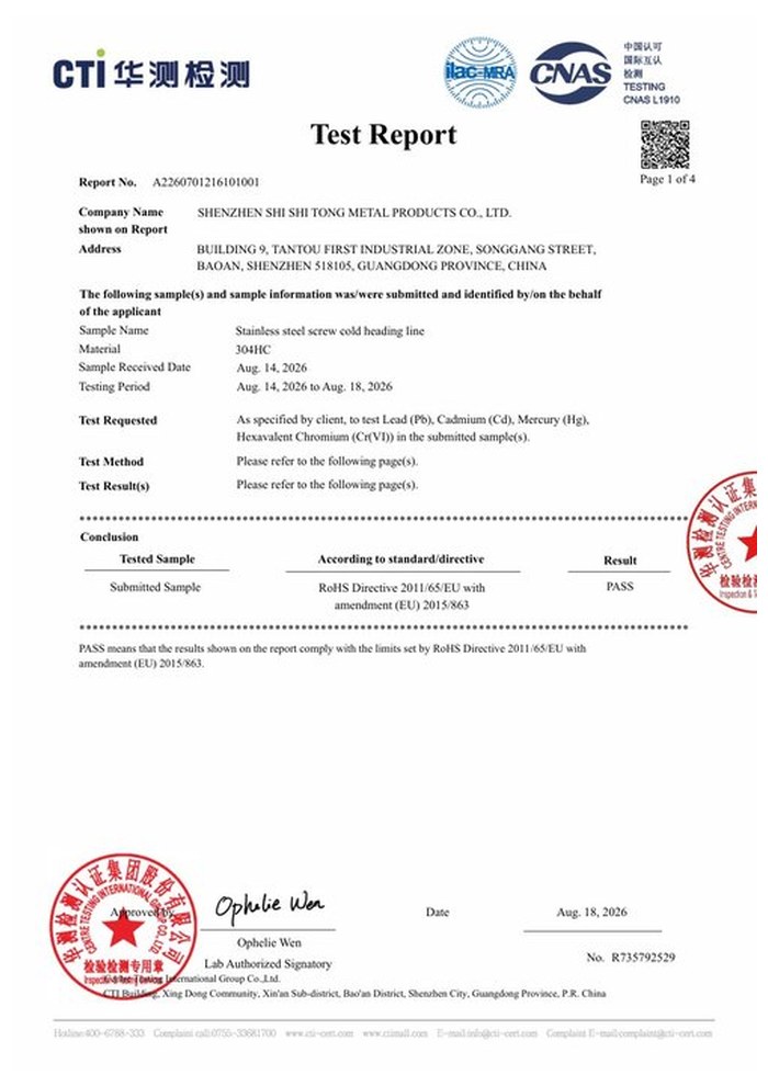
RoHS test report |
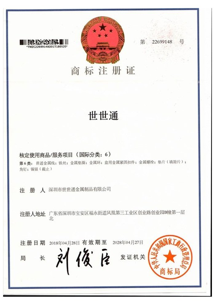
Registered trademark |
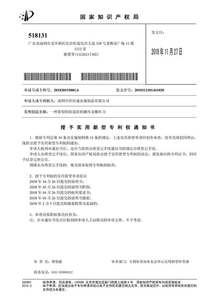
Patent: security screw and driver |
With each shipment we supply the material certificate, the inspection record with measured values, and the passivation records for the batch. The documents carry the drawing revision and the batch number, so a repeat order of low profile socket head cap screw dimensions can be compared with the original rather than assumed to match it.
More than 8,678 customers in 89 countries and regions have ordered from Shi Shi Tong; 87% of orders come from repeat customers and 56% through referrals. Most projects follow the same route: drawing review, first-article approval, then batches checked against that sample. On a dimensions page the first article is the reference: all four numbers are recorded against it and every later batch is compared with those values. Buyers visit during the process to review samples.
|
8,678+
customers served
|
87%
of orders from repeat customers
|
56%
of orders through referrals
|
89
countries and regions shipped to
|
Buyers and quality engineers visit for sample review, process discussion and supplier audits; the visit is arranged around production so the headers, the broaching station and the measuring bench can be seen on the day the parts run.

Customer group visit – sample review |

Customer group visit – process discussion |

Customer group visit – factory tour |

Customer visit – project kick-off |

Danish customer – drawing review |
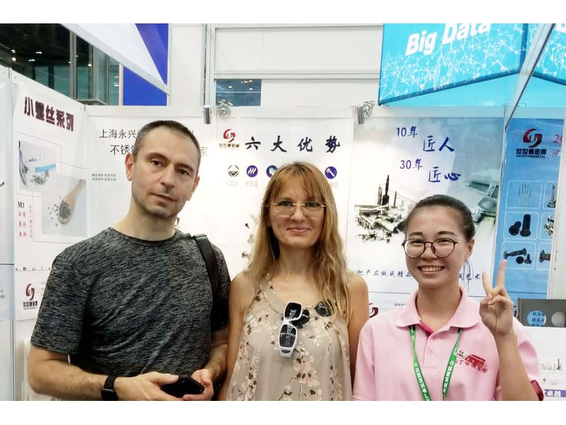
Industry exhibition – meeting customers |
Head diameter, head height, socket across-flats and socket depth, plus the thread and the overall length.
From the bearing face to the top face. Measuring over the fillet reads long and rejects parts that are correct.
Because it is bounded by the head height, and many drawings assume the standard. On a low head it has to be stated, because it decides whether the key reaches the floor.
Yes, measurably inside the socket and on the head. Plain stainless avoids that entirely, which is why the numbers on a plain part are the numbers in use.
Usually because the head height and socket depth were not measured. Thread and length are easy to check, and they are rarely the problem.
On a projector with the datum stated for each dimension, and the socket proved with the key. A caliper is not reliable at these sizes.
How a part is specified and confirmed when the dimensions are the requirement:
|
1
Send the drawing or the four dimensions
|
→ |
2
Datums and tolerances confirmed
|
→ |
3
First article measured and fitted
|
→ |
4
Batch production and repeat orders
|
Each step is confirmed with you before the next one starts; the measured values from the first article are the reference for every later batch.
For a quotation, send the drawing with head diameter, head height, socket across-flats, socket depth, thread specification and overall length, plus the datum for each.
|
Head diameter
|
Head height
|
Socket across-flats
|
|
Socket depth
|
Thread spec
|
Length
|
Sending a drawing? The form below does not take attachments. Email the PDF, DXF or STEP file to sst@szsst88.com with the part name and quantity in the subject line – the drawing is reviewed and a quotation follows.

 +86 13143444311
 sst@szsst88.com