
 +86 13143444311
 sst@szsst88.com


ENGINEERING GUIDE / FINISHED-PART INSPECTION
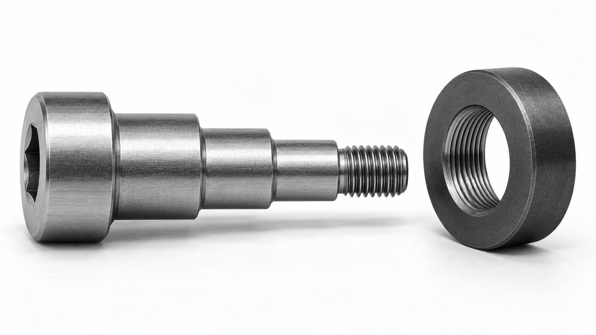
Thread gauge failure after plating often starts with an allowance that does not cover the deposited coating, uneven buildup, or a mismatch between the gauge and the specified finished thread. For a custom stepped screw, also check the smooth locating diameters: a passing thread does not guarantee a passing assembly.
Start with the drawing and the inspection condition. Separate dimensional growth from damage and gauge-selection errors before changing tooling or rejecting a lot. This guide focuses on external machine threads on custom screws and their adjacent locating features.
01 Acceptance condition · 02 Coating growth · 03 Failure diagnosis · 04 Assembly fit · 05 Prevention · Technical FAQ
1. Confirm what the gauge is supposed to accept
Record the full thread designation, drawing revision, coating specification and inspection stage. An external thread is normally checked with a thread ring gauge; an internal thread uses a thread plug gauge. A pitch gauge identifies spacing and is not a substitute for functional acceptance.
Confirm that the gauge is suitable for the required finished limits, within its calibration or verification controls, and free of contamination or damage. Keep pre-plate and final acceptance tools clearly identified. Do not select a looser gauge merely because the original one does not fit.
2. Understand how plating changes the thread
A coating grows on the flanks as well as on the crests. For a 60° external thread with a uniform deposited layer of thickness t measured normal to the surface, the pitch-diameter increase is approximately 4t. On a smooth cylindrical land, the diameter increase is approximately 2t. These are different geometric effects, so one allowance cannot simply be copied to every feature.
Vermont Gage explains this relationship and pre-plate calculations in its technical guidance on 60° plated threads. The relationship is a planning aid for the stated geometry, not a substitute for measurement or a universal rule for paint, heavy coatings and other thread forms.
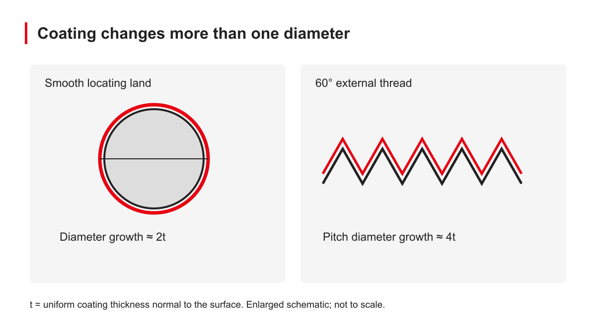
Use the specified thickness range and finished dimensional limits when establishing pre-plate targets. Nominal thickness alone does not describe local variation. An attractive coating at the head also does not prove that the thread has the required thickness or clearance.
Bossard’s corrosion-protection technical guide discusses non-uniform deposits and buildup at thread extremities. This is one reason to define measurement locations and examine the actual failure area instead of relying on a single average coating value.
3. Diagnose the symptom before changing the process
| Observed symptom | Possible cause | Useful next check |
|---|---|---|
| GO ring will not start | Entry damage, residue, local buildup or incorrect gauge | Check the first threads, gauge identity and handling history |
| GO ring starts, then binds | Local variation, thread form or lead error, or insufficient clearance | Record the stopping position; compare multiple parts and coating locations |
| Only some pieces fail | Variation in the pre-plate process, coating or handling | Keep lot identity and compare pre- and post-coating records |
| Thread passes; assembly still binds | Locating land, mating bore, seating or stack-up issue | Inspect the non-threaded features and actual mating parts |
These symptoms narrow the investigation; they do not prove a cause. Use the approved cleaning and inspection procedure first. Do not force the gauge through a tight thread, use it to remove coating, or chase the thread as an informal acceptance test.
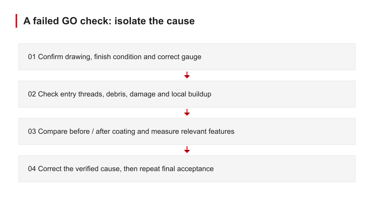
Where possible, compare traceable measurements before and after finishing on representative parts. Check the entry chamfer and visible damage, then use appropriate dimensional or profile measurements to investigate size, form and lead. A GO/NO-GO result alone does not identify which feature caused the failure.
If the issue appeared after a change in material condition, forming, thread production or finishing, review that change explicitly. The manufacturing-route comparison explains why a finished-part acceptance plan should follow the complete production sequence.
4. Check the locating steps in the real assembly
Machine vision and industrial sensors: a special stepped screw may locate a mounting bracket on one land, position a spacer on another, and fasten into a tapped support at the smaller end. Coating on the locating land reduces available clearance even if the terminal thread passes its ring gauge. Inspect the finished bore and land together, with seating and alignment requirements defined.
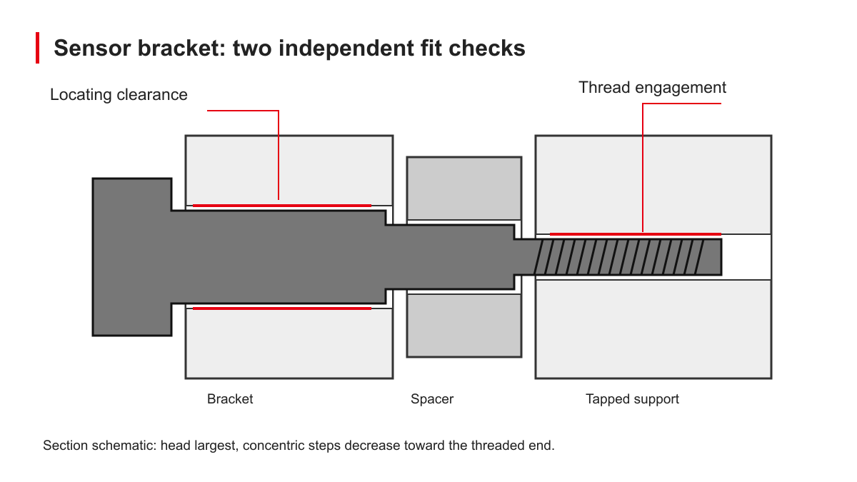
Robot grippers and end-of-arm tooling: replacement parts may need to enter locating holes without forcing or repeated adjustment. A fit that worked with uncoated trial parts must be rechecked after the specified production finish. Verify the intended movement, seating and service replacement procedure using representative mating parts.
Equipment covers and brackets: a screw can start correctly yet stop before the intended face seats. Check available thread engagement, runout clearance and the axial stack. Do not treat every seating problem as excessive plating. Use the step-diameter and axial-clearance design guide to define the non-threaded relationships.
5. Put coating and acceptance requirements on the drawing
A useful drawing-review package connects the coating requirement to the dimensions that control assembly. Specify the final requirements first, then agree a feasible manufacturing and inspection plan.
- Full thread designation, tolerance class and applicable acceptance standard.
- Coating system, required thickness range and measurement locations.
- Which dimensions apply before finishing and which apply after finishing.
- Final limits for locating lands, step lengths and seating relationships.
- Any approved masking areas and their effect on protection and function.
- Gauge selection, sample or lot acceptance plan, and traceable inspection records.
If rework is proposed, approve the method before it is used. Removing material or coating can change thread geometry, protection and assembly behavior. Reinspect the finished part after approved rework rather than accepting it solely because a gauge now fits.
Technical FAQ
How much no go gauge is acceptable?
Use the entry limit in the applicable gauging standard and approved inspection instruction. The rule depends on the thread system, gauge type and usable thread length; a single two-turn or three-turn rule is not universal. Check by hand without forcing the gauge and record the actual result.
What are the acceptable tolerances for threads?
They come from the complete thread designation and applicable standard: size, pitch, thread form, tolerance class and delivery condition. A nominal diameter such as M4 is insufficient. For a plated part, the drawing must make clear which limits apply before coating and which apply to the finished thread.
Why can a screw pass inspection before plating but fail afterward?
Coating occupies space on the thread flanks and can increase the functional size of an external thread. Insufficient allowance, uneven buildup or damaged entry threads can prevent a GO ring from advancing. Verify the specified finished limits and the gauge before deciding that the whole batch is oversized.
Can I reduce plating thickness to make the thread fit?
Only after an approved review of the specified coating system and performance requirements. Reducing thickness may undermine corrosion protection. The solution may instead require a revised pre-plate size, tighter process control or another approved finish. Confirm the final part meets both dimensional and coating requirements.
Does passing a thread gauge prove that a stepped screw will assemble correctly?
No. It does not validate the smooth locating diameters, step lengths, seating faces, mating holes or full joint behavior. Inspect those features and check representative mating components in the finished condition.
Send the failure evidence with your drawing
For a custom screw review, send the drawing revision, material and finish requirements, gauge identification, photographs of the affected thread, pre- and post-finishing records where available, mating-part details and required quantity. Mark the locating steps and seating faces that control the assembly.
Shi Shi Tong can review the custom geometry, manufacturing requirements and dimensional inspection plan for the project. Explore our special screw configurations or send your drawing and inspection findings.