Tel:
+86 13143444311
Email:sst@szsst88.com
Fax:+0086-755-27322278
Address:Building 9, First Industrial Zone, Tantou Industrial City, Songgang Street, Baoan District, Shenzhen 518105, Guangdong, China
Type:Stainless Steel Self Tapping Metal Screws, Pan Head Phillips Cross Recess Screws
Materials:Stainless Steel
Surface treatment:Plain, cleaned
Head Type:Pan Head
Size:M1 M2 M3 M4 M5 M6 M7 M8 M9 M10 M14
Drive type:Phillips cross recess (PH)
Thread:Coarse spaced self-tapping thread, partial length - plain shank under the head, thread only at the point
Number:878
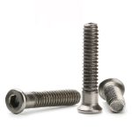
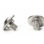
A pan head self-tapping screw in stainless steel, Phillips cross recess, plain finish, with a long plain shank and a short coarse tapping thread that ends in a gimlet point. The thread does not run the full length: it starts near the point and stops well short of the head, so most of the shank is a smooth shaft.
That proportion is the whole point of the part. It is used where the screw has to pass through a clearance hole in the front panel, cross a gap, and only then cut its thread into the panel or frame behind it. Four features decide whether the joint works: the plain shank length, the point where the thread starts, the point form, and the head that carries the clamp load into the sheet. Get three of them right and the fourth wrong, and the line stops.
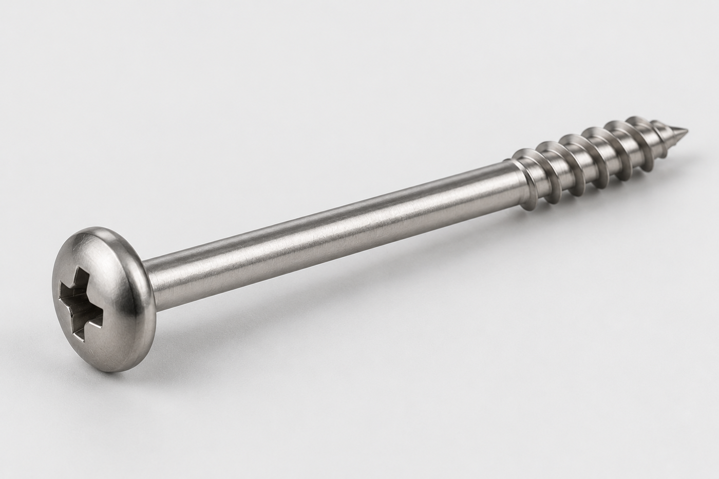
The part this page describes: pan head, Phillips cross recess, long plain shank, short coarse tapping thread, gimlet point, plain stainless.
On a fully threaded screw the shank and the thread are the same feature. Here they are two. The plain section is a shaft that locates: it sits in the clearance hole of the part being clamped and sets the position of that part relative to the one behind it. If the shank diameter is a close fit in the hole, the two panels are held on centre but the assembly has no float, and a stack-up of tolerance shows up as a hole that will not line up. If it is a loose fit, the panels drop into place and then slide before the thread bites.
The practical consequence is that the shank diameter and the clearance hole have to be specified together, and the shank length is a functional dimension rather than a leftover. It is the distance from the underside of the head to the first full thread, and it has to cover the thickness of the front panel plus the gap it has to cross, with the thread starting just before the second panel. On the drawing this is two numbers, not one: shank length and total length. A single overall length cannot be inspected into a working joint.
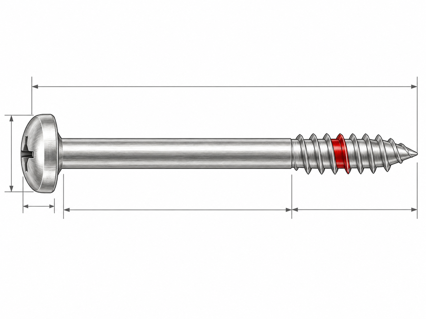
The two lengths that matter: head underside to first full thread, and head underside to the point. They are quoted and inspected separately.
Most failures attributed to “the screw stripped” on this geometry are actually thread-start position. Three outcomes are possible, and only one of them is a joint:
Thread starts too early. The first full thread is inside the front panel or inside the gap. The screw jacks the panels apart instead of clamping them, the hole in the front panel is chewed, and the assembly is loose with the screw fully seated. Thread starts too late. The plain shank runs out of travel before the thread reaches the second panel; the screw spins at the bottom of the hole and carries nothing. Thread starts where the second panel is. The thread engages, the head seats, and clamp load is generated across the stack.
We treat the panel stack as part of the drawing review. The customer supplies front panel thickness, gap, and rear panel or frame thickness; from that, the thread start position and the thread length are fixed, and the engaged thread count is checked against the load. When the stack changes later, the screw changes with it – the same part number cannot serve a 1.2 mm front panel and a 2.0 mm front panel.
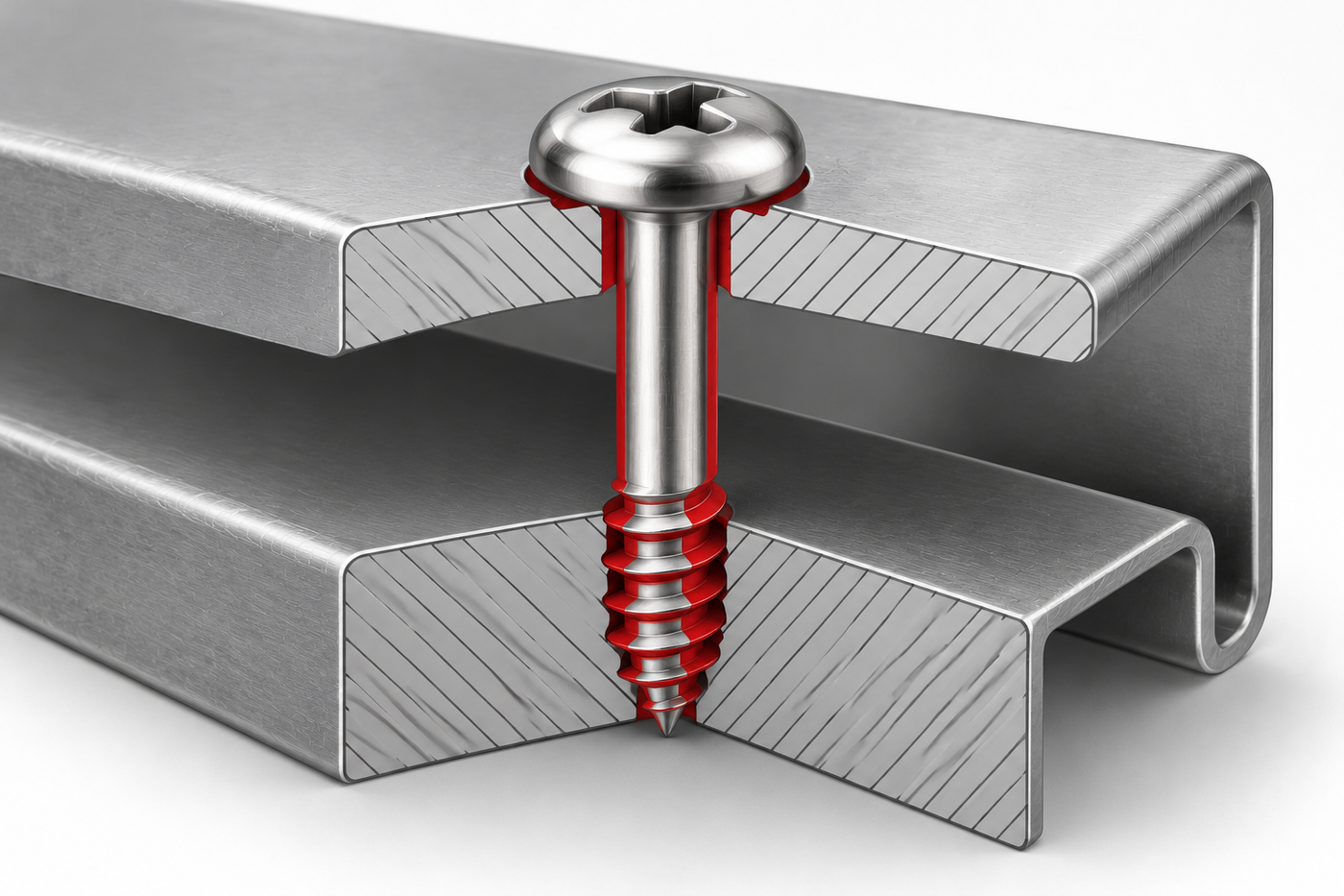
The intended joint: plain shank through the clearance hole and across the gap, thread engaged only in the panel behind. Highlighted in red.
The point is a hole-making feature, and it is paid for out of the same length budget as the thread. A gimlet point is a cone: it enters the hole, centring the screw, and it tapers the thread crests down to nothing at the tip. That taper carries no useful load. On a screw with a long thread the loss is invisible; on a short thread zone of a few millimetres it can consume a third of the threaded length.
So the point is specified by what it must not do as much as by what it must do. It must not push the far panel away before the thread catches. It must not protrude through the far side of a thin panel into a live area – in an enclosure a sharp stainless point standing inside the wiring space is a reject at final inspection, and in a battery cabinet it is a creepage distance problem, not a cosmetic one. The usable answer is usually to shorten the point and add thread, not to shorten the screw.
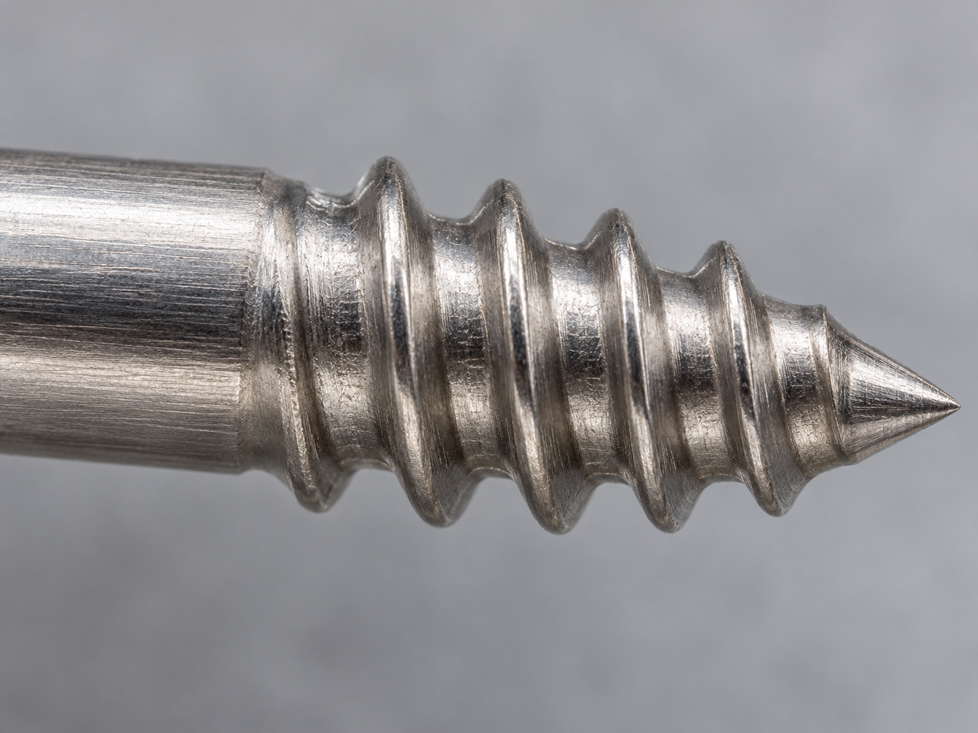
Thread run-out into the gimlet point. The taper below the last full thread is length that cannot carry load.
The recess is a torque coupling, and on a stainless screw driven by hand tools it is usually the first thing to fail. A cross recess cams out – the bit climbs the wall and spins out of the recess – when the bit is worn, when the recess is shallow, or when drive torque rises because the thread is cutting dry stainless. The design response is recess depth and wall thickness taken together: a deep recess in a low pan head leaves thin walls that spread under load, and a shallow recess in a tall head gives the bit nothing to hold.
The head is the other half of the same question. A pan head seats on a flat annulus, and that annulus is what turns torque into clamp load without dishing the sheet. On thin sheet the bearing area is the limit: too small and the panel dimples around the hole, the joint relaxes, and the screw looks tight while the panel is deformed. If the drawing needs more bearing area on the same head height, the part becomes a washer head – a different part with a different stack height, not a tweak to this one.
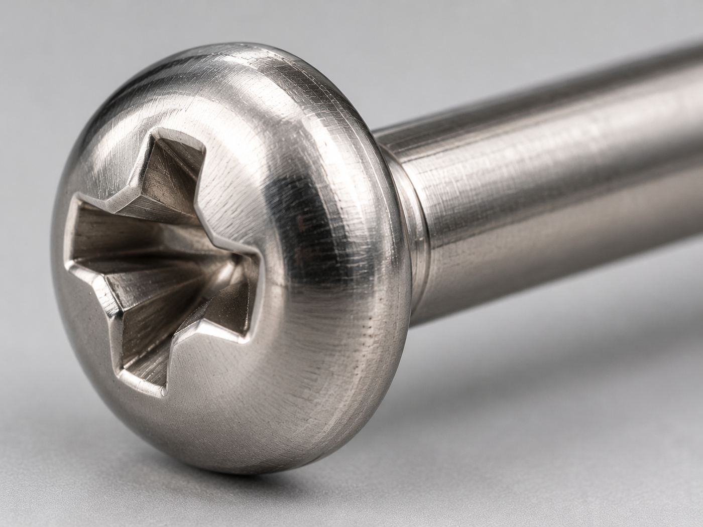
Recess depth against head wall: the two dimensions that decide cam-out on a dry stainless thread.
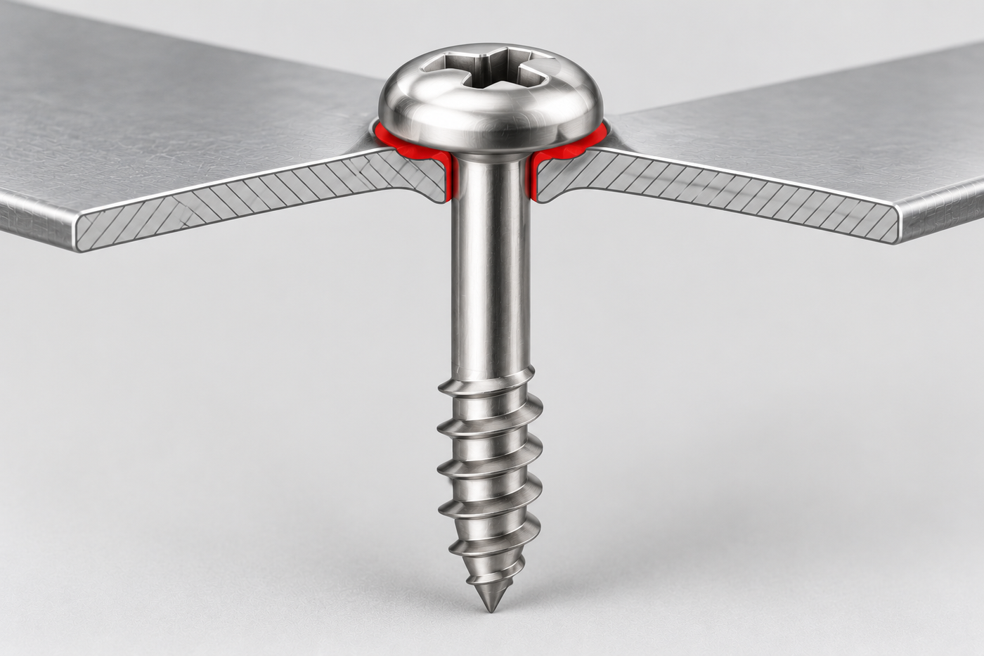
Bearing annulus and load path into thin sheet. Below a certain bearing area the panel dishes before the joint is tight.
Manufacturing
The body is headed from stainless wire in a single-die machine, then the thread is rolled between flat dies. Nothing is cut away. Rolling displaces material, so the grain follows the thread profile instead of being severed across it, the crest is work-hardened by the die rather than left as a machined edge, and there is no chip to trap in the recess. On a tapping screw that last point matters more than it sounds: a cut thread leaves a burr at the point and along the run-out, and a burr is what tears the sheet and what fails a visual check.

 |
 |
Where the drawing needs a shank that stays straight over a long run, or a point form the die cannot produce in one blow, the part moves to a secondary operation and is quoted as a separate step rather than promised inside the heading cycle. Long slender shanks are where that conversation usually starts: the heading is easy, holding straightness after it is the work.
This part ships plain. There is no zinc, no black oxide, no coating thickness on the flanks, so the thread geometry that leaves the rolling dies is the geometry that arrives at the assembly line. For a tapping screw that is a real advantage: thread form is what generates the joint, and a coating that builds 8 to 15 micrometres on the crest changes the torque needed to drive the screw and the torque that strips the hole. Plain also removes the hydrogen embrittlement question that comes with electroplating high-strength parts, and there is no film to flake off under a washer face.
What it does not buy is immunity. Stainless resists corrosion through its oxide layer, and that layer needs oxygen and a clean surface; a grade chosen for a washdown area is a different grade from one chosen for an indoor cabinet, and A2 (304 system) against A4 (316 system) is the decision that gets made at drawing review, not at the plating line. The other exposure is galling: stainless on stainless, dry, at speed, will cold-weld at the contact patch and smear metal off the thread. It shows up as a screw that tightens and then seizes, or a thread that arrives at the next station with a torn flank.
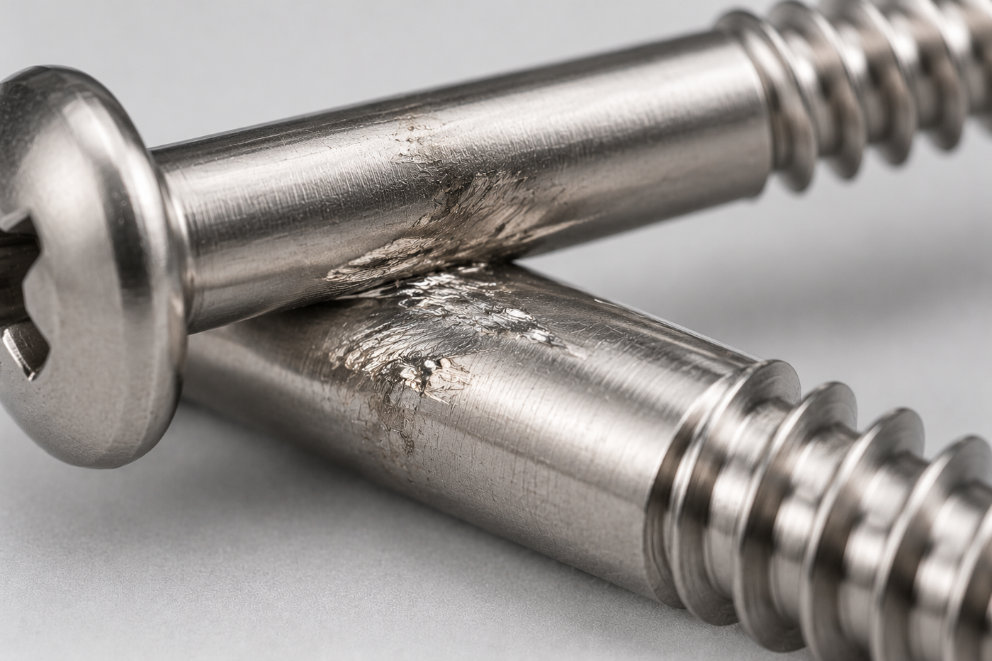
Galling at a stainless-on-stainless contact patch: material transfer, not wear. It is managed by drive strategy and surface condition, not by torque alone.
The controls are procedural as much as metallurgical: a lubricated or waxed thread where the drawing allows it, a controlled drive speed rather than a hammer drill on full power, correct bit condition, and a torque window agreed with the customer instead of “as tight as it goes”. Passivation, where specified, is a cleaning operation that restores the oxide layer after machining – it is not a coating and it does not add thickness to the thread.
Inspection
Inspection follows the three places this part fails in service: the thread, which decides whether the screw grips or strips; the shank, which decides whether the joint lines up; and the head and recess, which decide whether the driver can put torque in without camming out. Everything is gauged on the finished part in the condition it ships in, which for this part means plain, cleaned stainless with no coating to hide a thread.
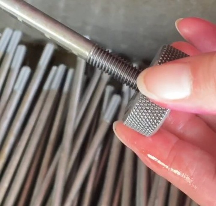
Tapping thread checked GO / NO-GO on the finished part |
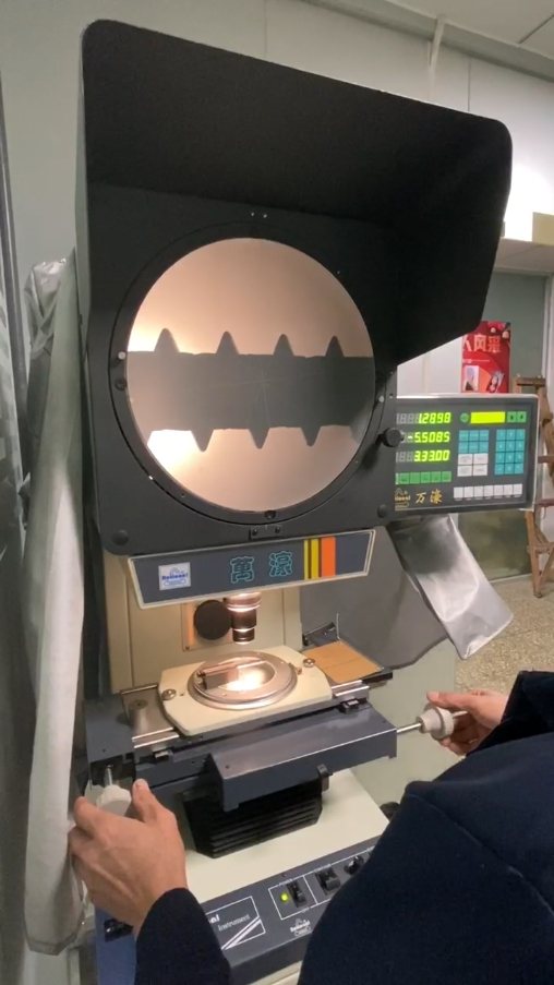
Shank diameter, thread length and point on the projector |
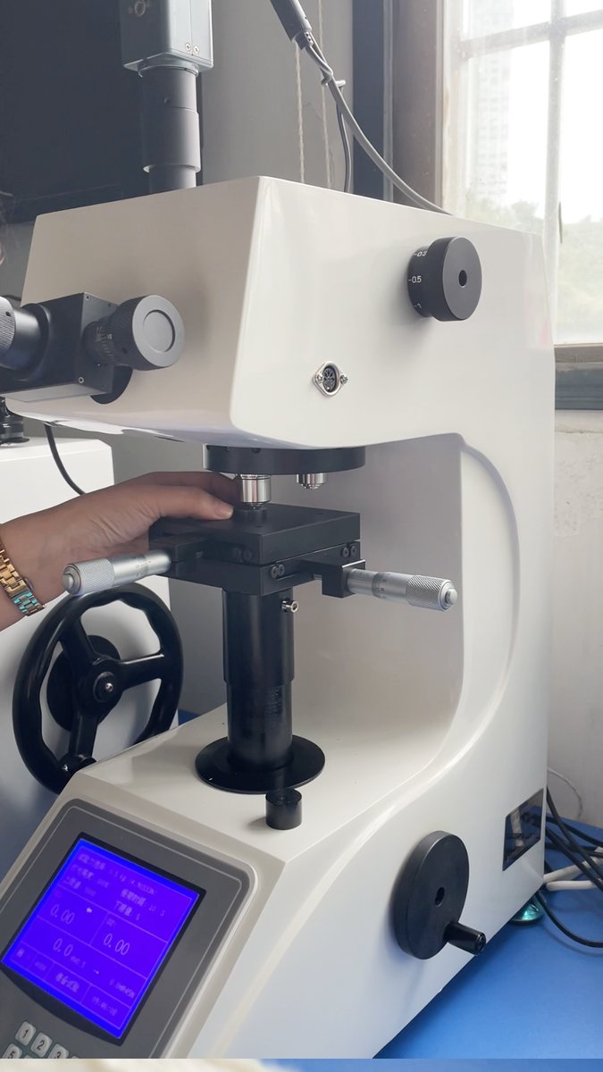
Hardness where the drawing states a property class |
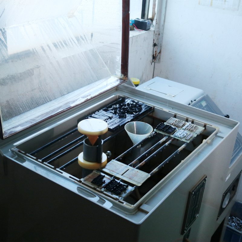
In-house salt spray only where a corrosion record is specified |
Thread and dimensions are checked as the part ships; a plain stainless screw has no coating thickness to compensate for, so the gauged thread is the working thread.
Two rules sit behind that routine. The first is that the inspection record belongs to the same parts that ship: same drawing revision, same material lot, same heat or passivation batch. A report from another lot is not evidence for this one. The second is that internal testing and third-party testing are kept apart. In-house salt spray, hardness and torque results are internal records; when a customer or a regulation needs a third-party report, it is agreed before the lot runs, not assembled afterwards.
Certificates
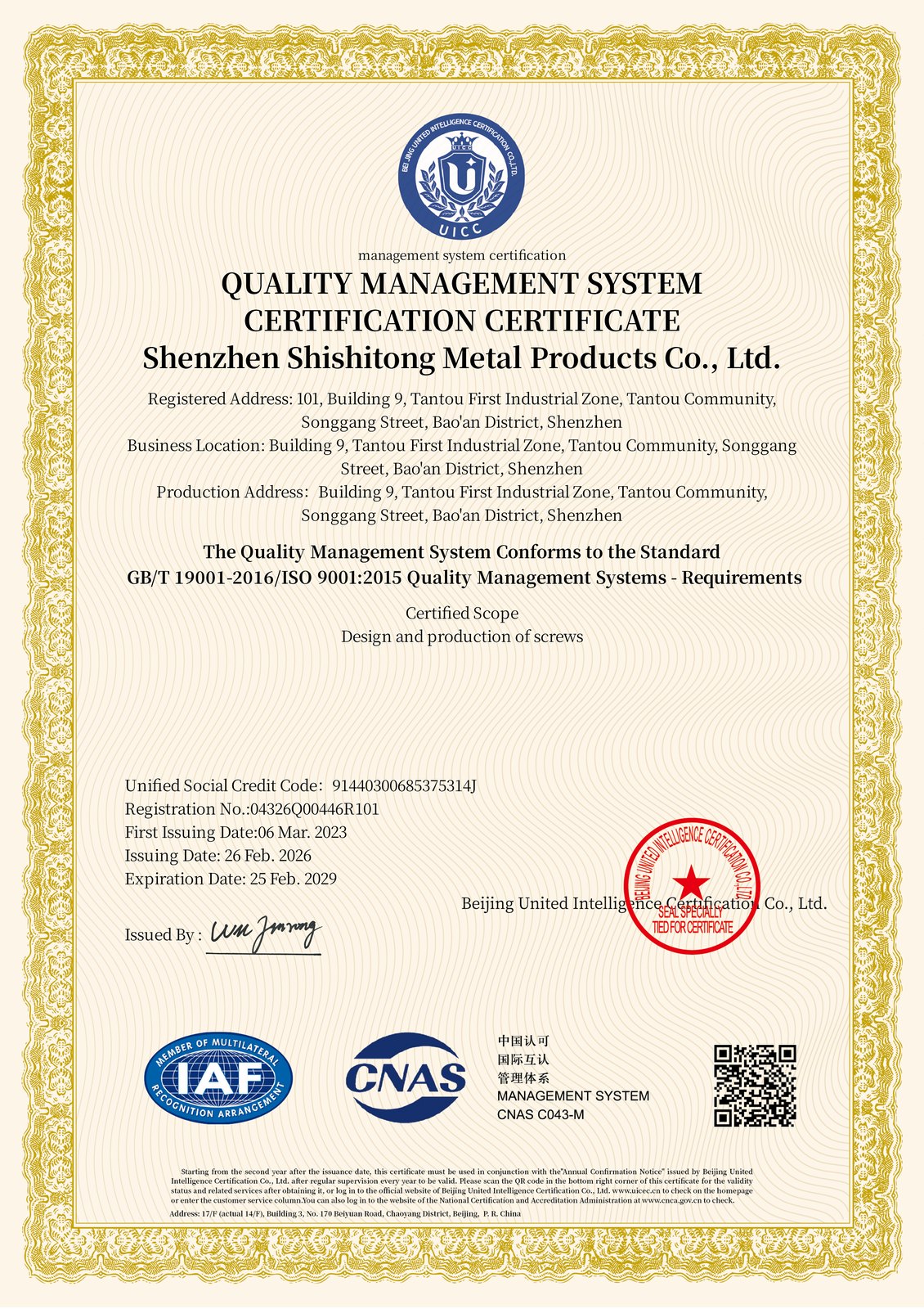
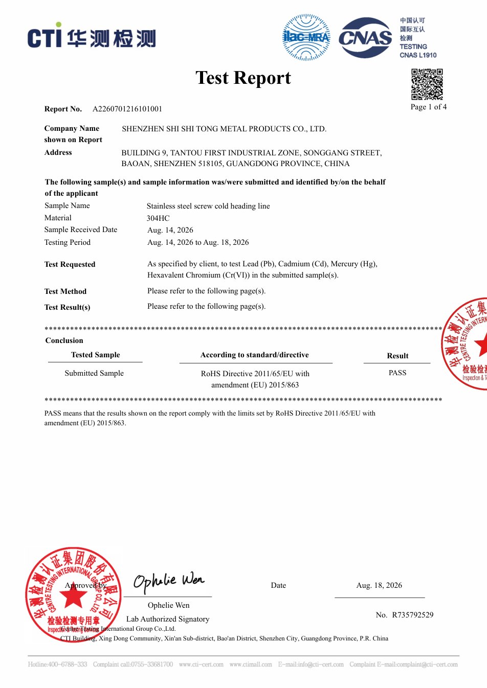
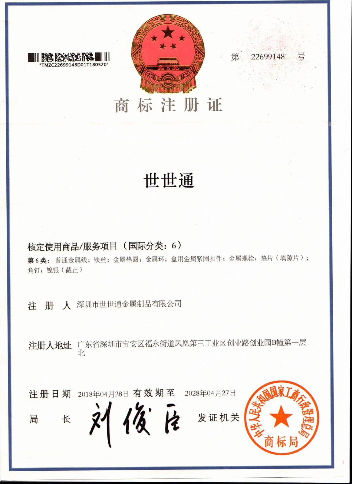
The quality management certificate, the RoHS position for the stainless material family, the registered trademark and the patent are the four documents buyers ask for most often on this product family. Material certificates travel with the lot. A lot-specific dimensional or test report is issued against that lot, and any third-party report is arranged as part of the order rather than promised as a standard document.
|
ISO 9001:2015 – quality management system |
RoHS – material family position |
|
Registered trademark – SHISHITONG |
Patent certificate – fastener design |
The certificates are linked to the certificate page so a buyer can open the full document rather than read a thumbnail. What they do not do is turn into a claim: ISO 9001 covers the management system and its stated scope, RoHS covers the material family position, and neither of them is a statement that every dimension on every lot has been third-party verified.
APPLICATIONS
The problem. Enclosure work is thin galvanised or powder-coated sheet, usually 1.0 to 1.5 mm, assembled at speed with a clutch-controlled driver. Three things go wrong on a self-tapping screw in that joint: the thread strips in the single sheet it engages, the head dimples the panel and the door line moves, or the point crosses the wiring space and fails final inspection.
Why it happens. A coarse tapping thread in 1.2 mm sheet grips on one or two crests, so the strip torque is low and any variation in hole size or drive clutch decides the outcome. Coating on the sheet does not add strength; it adds thickness that the thread has to displace, which raises drive torque at exactly the moment the recess is least able to take it.
What we control. Thread length is matched to the sheet it engages so the screw does not jack the frame, the shank diameter is set against the clearance hole in the front panel, the point is shortened so it stays inside the enclosed space, and the recess is checked for depth against the head wall so a worn bit still drives. Where the panel is too thin for the load, we say so at drawing review instead of quoting a longer screw.
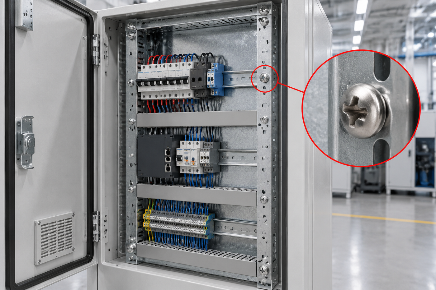
Enclosure frame and mounting plate: the joint is one sheet thick, so thread engagement and point length decide the result.
The problem. AHU casing panels are large, thin, and screwed along a frame that vibrates for the life of the unit. A joint that is tight at commissioning relaxes once the fan runs: the sheet frets under the head, the hole opens, and the panel starts to rattle or leak at the gasket line.
Why it happens. Clamp load on thin sheet is limited by bearing area, not by driver torque. Once the panel dishes, further torque goes into deforming the sheet rather than tensioning the joint, and vibration does the rest. Condensate makes it worse: a coated carbon screw loses its protection at the first scratch under the head, which is precisely where the water sits.
What we control. Stainless body with a plain finish so there is no coating to chip at the bearing face and no zinc layer to fail in a wet casing; head bearing area and head height checked against the panel thickness so the sheet does not dish; thread length set to the frame section it engages, not to the panel thickness alone. On gasket lines we ask for the compressed gasket thickness, because that number moves the effective stack and therefore the thread start position.
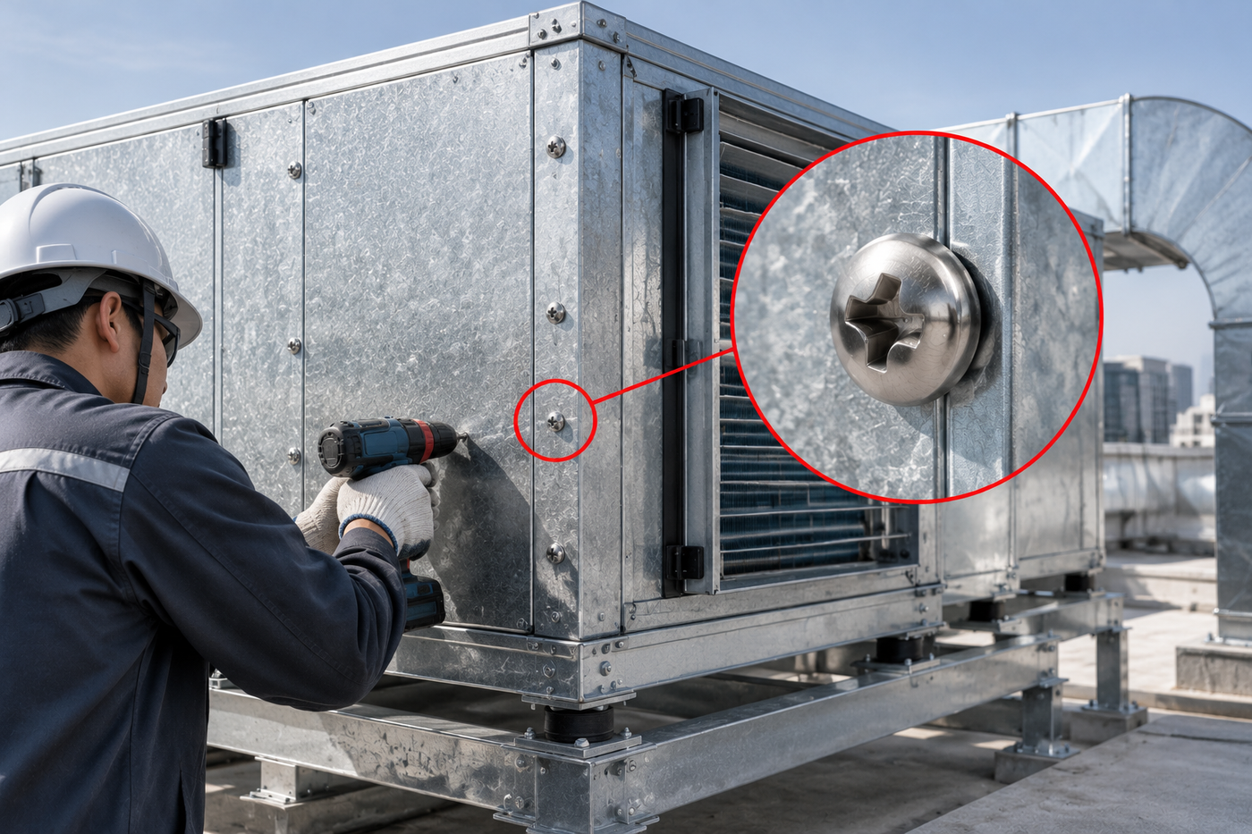
AHU casing: the gasket sits inside the stack, so the thread start has to be set from the compressed stack, not the bare panel.
The problem. A stationary cabinet or rack enclosure is sheet steel with modules, shelves and cable management behind the panels. The assembly needs fast, repeatable panel fixing, and it needs the inside of the cabinet to stay electrically clean. A screw point standing proud of a panel into the module space is not a cosmetic defect; it changes a creepage distance.
Why it happens. Point length is chosen for the sheet, and the sheet is thin, so the point exits the far side. Burrs from a cut thread or a worn die make it worse, and a burr also sheds a particle into the cabinet. Where panels are powder coated, the coating thickness at the hole varies and the drive torque scatters from batch to batch.
What we control. Point length limited so the tip stays inside the panel or clears the module space by an agreed margin; rolled thread so there is no burr at the point or the run-out; thread length set from the frame section; shank diameter set from the clearance hole so the panel lands without being forced. For module shelves and rack rails, the same part is re-checked against the rail thickness rather than carried over from the cabinet skin.
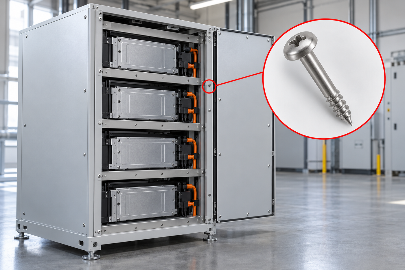
Stationary cabinet and module rack: point length and burr control matter because the far side is an electrical space.
CUSTOMERS
Repeat business is the largest part of our order book
Customers visit the factory to review Stainless Steel Self Tapping samples, check the Pan head and Coarse spaced self-tapping thread on first-article parts, and inspect the Plain finish before shipment – and most of the next order comes from the same accounts.
|
8,678+
Customers served
|
87%
Repeat orders
|
56%
Referral orders
|
89
Countries and regions
|
|
Customer visit – Stainless Steel Self Tapping first-article review |
Audit on the shop floor – Pan head form and Coarse spaced self-tapping thread checked |
Customer touring the Shi Shi Tong shop floor – Stainless Steel Self Tapping line |
Denmark customer visiting Shi Shi Tong – Stainless Steel Self Tapping order review |
|
Shi Shi Tong at an international exhibition – Stainless Steel Self Tapping on display |
Customer delegation at Shi Shi Tong – Stainless Steel Self Tapping batch discussion |
Customer team visiting Shi Shi Tong – Plain sample comparison |
Customer reviewing first-article Stainless Steel Self Tapping parts with our QC team |
How do I specify the shank length on the drawing? Give the panel stack, not just the total length: front panel thickness, the gap the shank has to cross, and the thickness of the panel or frame the thread engages. From that, shank length (head underside to first full thread) and thread length are both fixed and can be inspected. A single overall length leaves the thread start position undefined, which is where joints fail.
How much thread engagement does this joint need? The useful target is full thread engagement through the engaged panel plus a margin below it, with the point clear of anything behind. On thin sheet the practical limit is set by how many full crests the sheet can support before it strips, and by the load the joint carries. We check the engaged length against the panel thickness at drawing review and say when a thicker panel, a larger diameter or a finer pitch is the honest answer.
Can this screw drill its own hole? No. This is a thread-forming tapping screw with a gimlet point: it needs a pilot or clearance hole. A self-drilling screw with a drill point is a different part with a different point geometry, and we quote it as such rather than describing this screw as self-drilling.
Why plain stainless instead of a plated screw? Because the thread is the function. Plating builds thickness on the crest and changes both drive torque and strip torque, and it introduces a hydrogen embrittlement route on high-strength parts. Plain stainless keeps the rolled thread geometry and removes the coating failure mode at the bearing face. The trade is that the grade has to be chosen for the environment – A2 (304 system) or A4 (316 system) – instead of relying on a coating.
How do I keep stainless screws from galling during assembly? Control the drive, not just the torque. Use a good bit in good condition, keep drive speed moderate, and where the drawing allows it use a lubricated or waxed thread. Set a torque window with the customer rather than driving to refusal, because a dry stainless thread that seizes has already damaged the flank before the clutch cuts out.
Does the point have to stay inside the panel? It depends on what is behind the panel, and that is a question for the drawing. In an enclosure or a battery cabinet the answer is usually yes, for creepage and for inspection; in an open frame it may not matter. We set point length from that requirement and from the panel thickness, and the same body can be supplied with a shorter point where the space behind is live.
This page covers the long-shank, short-thread variant in stainless. Adjacent parts differ in the feature that decides the joint, so they are worth reading together rather than substituting one for another:
Most of the decisions on a part like this are made before a quote exists: which panel the thread engages, how far the point may travel, what the drive station can hold. That is a drawing conversation, and it is faster with the stack on the table than with a description. Buyers and engineers visit the plant, walk the heading and rolling area, and sit with the inspection bench where their part will be gauged.
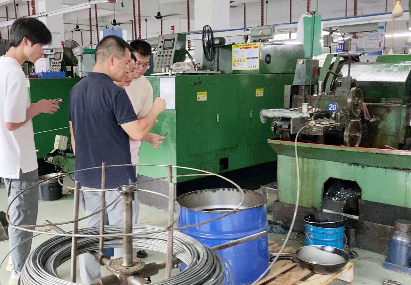
Customer visit on the Shi Shi Tong floor: heading, thread rolling and the inspection bench, on the same walk.
Samples follow the same rule as production: the sample is the part that will be gauged, from the die that will run the lot, with the drawing revision recorded against it. When the sample is approved, the thread start position and point length become fixed dimensions rather than intentions.
Next step. Send the panel stack, the material grade and the drawing revision through the drawing review entry. We will come back on thread length, point length and the drive window, or say where the joint needs a different part.

 +86 13143444311
 sst@szsst88.com