Tel:
+86 13143444311
Email:sst@szsst88.com
Fax:+0086-755-27322278
Address:Building 9, First Industrial Zone, Tantou Industrial City, Songgang Street, Baoan District, Shenzhen 518105, Guangdong, China
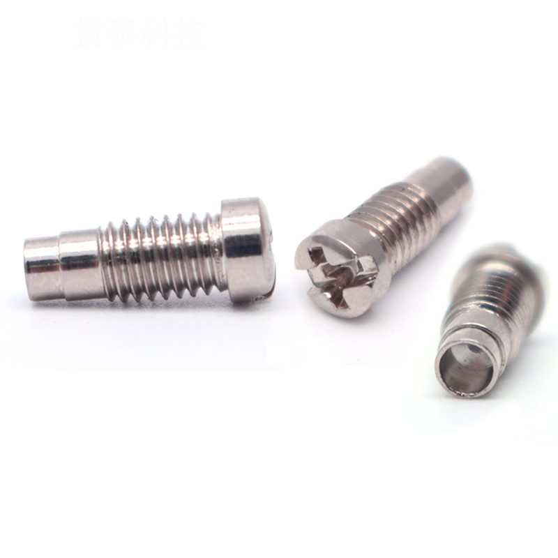
Type:303 Stainless steel CNC machining parts
Materials:303 Stainless steel
Surface treatment:Plain
Head Type:Fillister head
Size:M1 M2 M3 M4 M5 M6 M7 M8 M9 M10
Number:1492
The listed configuration uses 303 stainless steel, a fillister-style head and a plain finish. The drive information is shown as Phillips/slot and requires definition on the part drawing. CNC machining is reviewed around the head, body and any threaded features needed by the customer’s assembly.
Specify head diameter, height, upper contour and the underside that locates against the mating part. Include edge radii and the transition to the body. Where the head enters a recess, provide the receiving profile and clearance so the finished component can be checked against the complete seating interface.
State whether the design needs a Phillips recess, a straight slot or a defined combined feature. Provide width, depth and the applicable tool dimensions for the selected arrangement. Confirm the intended method of installation so the machining drawing and inspection plan describe the same drive interface.
Dimension any steps, bores, grooves or threaded portions present in the design and relate them to functional datums. Distinguish locating surfaces from clearance surfaces. This allows machining and measurement effort to focus on the relationships that determine fit rather than treating every dimension as equally critical.
Review the Head, Drive and Body Drawing
Where threads are required, specify their size, pitch, class and usable engagement length. Identify internal and external threads separately and show reliefs or runout where they affect assembly. If the part is unthreaded in a particular configuration, the drawing should make that clear instead of relying on a general fastener template.
Shi Shi Tong reviews tool access and workholding for the 303 component before confirming the machining route. Features that must align across operations are identified from the drawing. Any proposed changes to corner geometry, reliefs or setup surfaces are resolved before sample approval.
The measurement plan can cover the head profile, drive dimensions, body fits and specified positional relationships. Define burr and edge-break requirements around the slot or recess. Use the intended driver and mating component for functional checks where individual measurements do not fully demonstrate acceptable assembly.
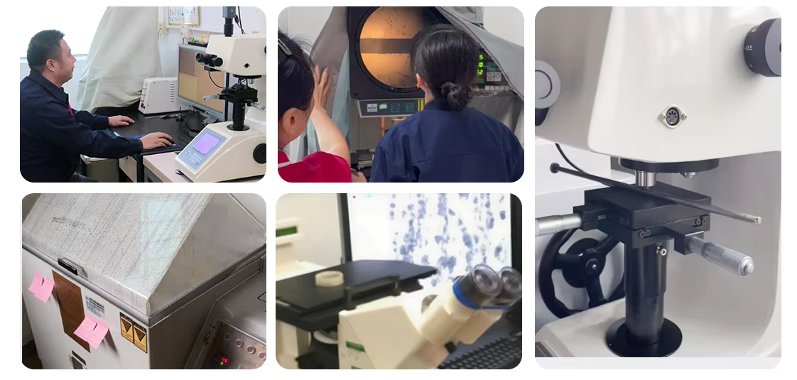
Identify the material standard and any required condition or traceability records. Define acceptable machining marks, cleanliness and any treatment beyond the listed plain finish. Relevant company documents can support supplier review, while the ordered component requires its own agreed dimensional and material evidence.
Keep the accepted drive type, head profile and body datums together in one controlled revision. Changes to the tool interface or mating recess should trigger a review of the relevant sample checks. Repeat-order acceptance should refer to the approved drawing and records rather than a broad product name.
Send a model and drawing showing the fillister head, selected drive arrangement and body features. Include the 303 material specification, finish, quantity, inspection requirements and delivery target. Highlight the mating surfaces and tool interface so the quotation addresses the features that control assembly.

 +86 13143444311
 sst@szsst88.com