
 +86 13143444311
 sst@szsst88.com
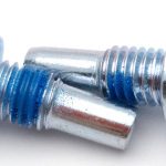
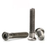
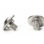

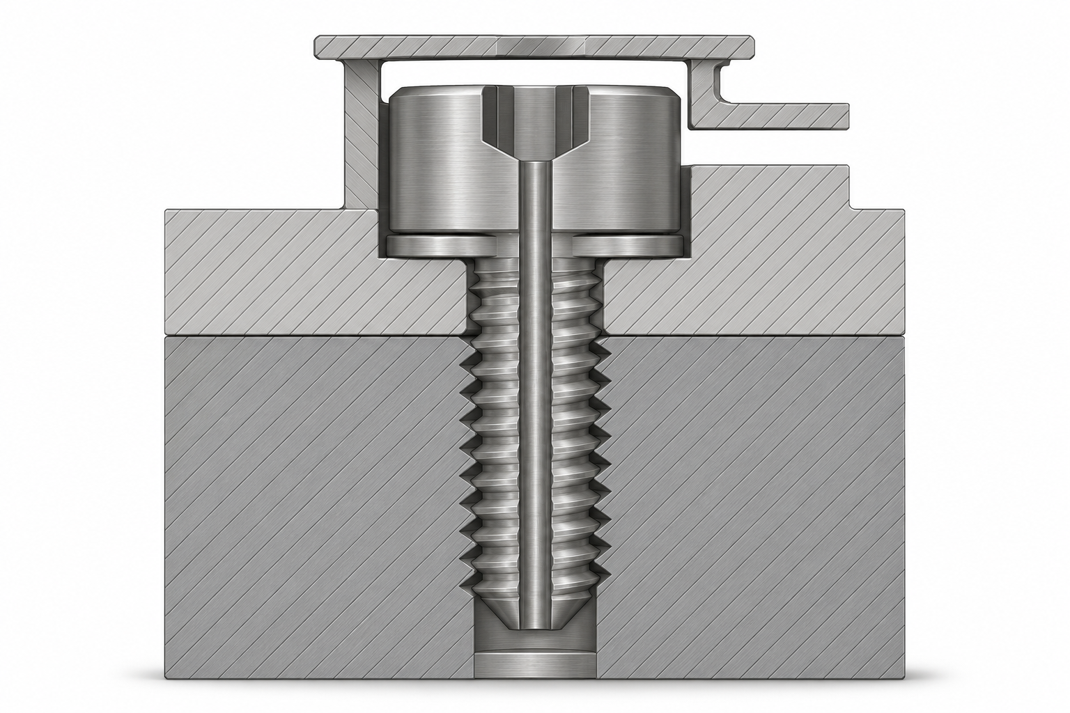
Load lock vented screws need an open gas path in the final assembly, not just a hole through the loose fastener. Check the space above the drive recess, the pocket beneath the screw tip and any volume enclosed by a washer. A cover or tolerance change can restrict one of these connections even when the screw meets its individual drawing.
Define the assembly and cycle requirement
A load lock transfers samples between atmosphere and a process chamber without venting the main chamber, as explained in Kurt J. Lesker’s load-lock overview. Its internal fasteners therefore operate within a chamber that repeatedly changes pressure. This article concerns fasteners holding internal fixtures, covers or brackets; a chamber door or pressure-boundary joint requires its own approved sealing design.
Write the acceptance requirement around the actual assembly: which trapped volume needs an escape route, where that route joins the load-lock volume, and what pump-down behavior the equipment owner must verify. Do not replace an equipment acceptance criterion with a statement that the screw is ‘vacuum suitable’.
Record the cover, washer and fixture revisions used with the screw. Two assemblies sharing the same screw can have different outlet clearances. Inspect only after safe shutdown, isolation and venting under the equipment manufacturer’s maintenance procedure.
Check the head outlet and surrounding pocket
For a screw with an axial hole opening into its socket, the drive recess acts as part of the gas path. A flat cap pressed over the head can enclose that recess. A cap held above it may leave a gap, but that gap still needs a route to the chamber at its edge. Trace the route across both interfaces rather than checking only the vertical distance.
A plain washer does not automatically block an axial bore through the center of the screw. Its separate risk is an enclosed annular pocket around the shank or under the bearing surface. Vented-washer designs address trapped gas at washer interfaces. Whether a washer needs its own vent feature depends on the pocket geometry and its existing connections; it is not a reason to replace every washer indiscriminately.
| Interface | Possible restriction | Drawing evidence to request |
|---|---|---|
| Drive recess to cover | The cover contacts the top face or closes the socket opening | Minimum assembled head-to-cover gap, including cover deflection |
| Covered head pocket to chamber | A surrounding wall encloses an otherwise open gap | Section through the lateral exit, not only through the screw axis |
| Washer to bearing surface | An annular pocket lacks a connection to the axial bore | Actual washer profile and the proposed pocket escape route |
| Screw tip to blind-hole bottom | The inlet seats against the bottom or drill-point geometry | Tip geometry, usable hole depth and worst-case insertion |
Calculate the minimum outlet clearance
Define H as the distance from the screw’s head-bearing plane to the cover’s inner surface. Define h as the installed head height above that bearing plane. Let δ be the maximum inward cover movement allowed in the operating condition. For this simple axial stack:
gmin = Hmin − hmax − δmax
With selected drawing values H = 6.20 ± 0.10 mm, h = 5.80 ± 0.05 mm and δmax = 0.10 mm:
gmin = 6.10 − 5.85 − 0.10 = 0.15 mm.
This is a geometric clearance calculation, not a recommended vacuum-flow clearance. The lateral exit and required conductance still need assessment.
If a washer is added below the head, include its installed thickness in h or redefine the datum consistently. Do not subtract it twice. If the cover can bow or the screw tilts within clearance, the minimum local gap may differ from the nominal axial result. Include those effects where the design permits them.
A positive result prevents nominal contact under the stated assumptions; it does not establish a sufficiently low flow resistance. A narrow, long slot can be a more restrictive part of the route than the bore. Increasing the screw bore cannot compensate for an outlet that is closed.
Check tip clearance without losing engagement
Shortening a screw may open a pocket below the tip, but it also changes the available thread engagement. Check both requirements against one datum. Measure how far the tip enters the receiving hole after the bearing surfaces seat, and compare that with the actual bottom envelope. The drilled depth, full female-thread depth and usable screw engagement are different dimensions.
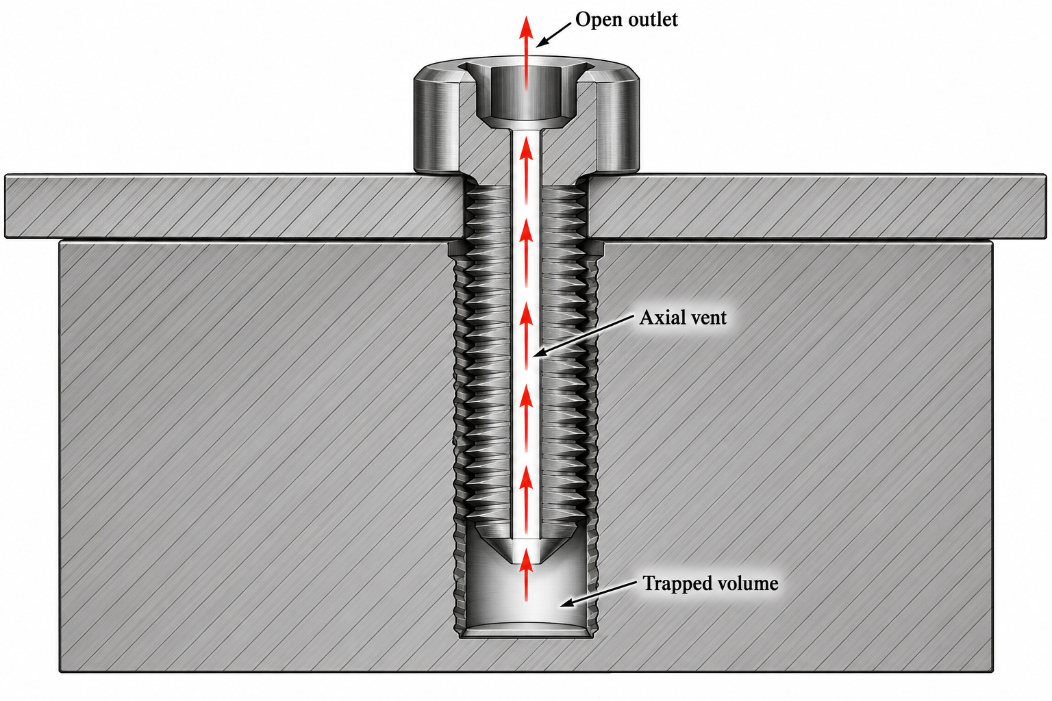
For a flat-bottom geometric model, the minimum tip gap is the minimum bottom depth from the assembly datum minus the maximum inserted tip position. A conical drill bottom needs an envelope check using the real tip and bore-mouth geometry. Do not use the deepest point of the drill cone as if the entire screw tip could reach it without interference.
After any length change, verify the full engaged thread interval, bottoming margin, bearing contact and installation load. An open gas path is not acceptable if the joint loses its required mechanical function.
Verify the assembled route
- Inspect the component. Confirm bore continuity and the dimensions that control its location, alongside the external thread and head geometry.
- Inspect the stack. Assemble the specified washer, fixture and cover. Verify the gap at the most restrictive location using a method appropriate to access and size.
- Inspect the exit. Confirm that the head pocket connects to the chamber rather than to another enclosed pocket.
- Check limiting combinations. Review the maximum head projection and minimum cover position, including the permitted mechanical movement.
- Evaluate the equipment cycle. Compare the agreed pressure trace or transfer condition with the equipment owner, keeping other relevant settings controlled.
A loose-screw bore check is component evidence. It does not prove the final assembly’s pumping performance. Conversely, one successful equipment cycle does not replace dimensional controls that keep later batches within the approved assembly envelope.
Specify the drawing and inspection evidence
For custom titanium screws, provide the material purchasing specification, finished condition, bore geometry, head dimensions and mating assembly section. Mark the functional clearance rather than relying on a picture of an open-looking pocket. Include minimum remaining wall where the bore approaches the drive recess or thread root.
Separate supplier-controlled features from equipment-level checks. The fastener manufacturer can review screw geometry, process feasibility and agreed component inspection. Cover movement, chamber-side flow and the transfer-cycle acceptance belong to the integrated assembly assessment. Use a joint drawing review to make that responsibility clear before ordering.
Technical FAQ
Does a counterbore always block a vented screw?
No. An open counterbore can leave the head outlet exposed. The risk arises when a cover, seal or surrounding feature encloses the outlet or restricts its route to the chamber.
Will an ordinary flat washer seal the central vent?
Not necessarily. A washer around the shank usually leaves the axial bore untouched, but it may enclose a separate pocket beneath the head. Review that pocket independently.
Is 0.15 mm enough clearance above the screw head?
That number is the result of the selected geometric stack in this article, not a general design limit. Required clearance depends on the entire flow path, tolerances, movement and equipment requirement.
Can the screw simply be shortened to open the tip inlet?
Only if the revised length still provides the required engagement and joint function. Verify tip clearance and full-thread engagement together.
Must the vent connect to atmosphere?
No. For an internal vacuum fixture it must connect the trapped pocket to the chamber volume. Creating a passage across the chamber pressure boundary would introduce a different sealing problem.
Review the screw and the mating assembly together
Send your screw drawing, a section through the mating hole, material specification, quantity and critical acceptance requirements. Shi Shi Tong reviews the geometry, manufacturing route and inspection requirements before confirming a custom screw proposal.
Copy this email address and attach your drawings in your email service:sst@szsst88.comOpen Email App →
If your email app does not open, copy this address into your email service.