Tel:
+86 13143444311
Email:sst@szsst88.com
Fax:+0086-755-27322278
Address:Building 9, First Industrial Zone, Tantou Industrial City, Songgang Street, Baoan District, Shenzhen 518105, Guangdong, China
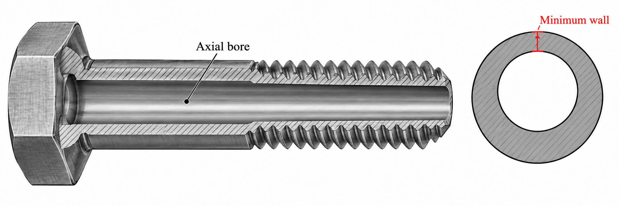
Hollow custom screws need more than a bore diameter. The critical checks are the remaining load-carrying section, the minimum local wall and the bore’s relationship to the exterior geometry. A hole can be the correct size but still leave one side too thin. Start with the passage’s function, then define the geometry and inspection method that protect it.
A central opening may carry a cable, provide a gas path, reduce mass or accommodate another component. These functions are not interchangeable. A cable passage needs suitable edge treatment; a vent needs an unobstructed route; a pressure-carrying passage needs sealing and pressure qualification. A hole shown on a screw drawing establishes none of those performance requirements by itself.
For a compact sensor assembly, a sharp exit can damage insulation even when the cable passes freely. For a lightweight linkage, reducing mass may be less important than retaining stiffness or fatigue resistance. Define the interface at the head and at the tip, the required internal surface and any restriction on debris or lubricant.
For a concentric circular bore through a smooth round section, A = π(D² − d²)/4. The remaining-area ratio to a solid section is 1 − (d/D)². The following geometry calculation uses D = 6.0 mm and compares bore sizes at the same outer diameter.
| Bore d | Remaining area | Area retained | Nominal stress at 1,000 N |
|---|---|---|---|
| 0 mm | 28.27 mm² | 100% | 35.4 MPa |
| 2.0 mm | 25.13 mm² | 88.9% | 39.8 MPa |
| 3.0 mm | 21.21 mm² | 75.0% | 47.2 MPa |
| 4.0 mm | 15.71 mm² | 55.6% | 63.7 MPa |
Stress here is F/A for a centred axial load on the stated smooth section. The values are not allowable loads or material strength data. At a threaded section, nominal major diameter is not the appropriate smooth outside boundary; thread-root geometry, stress concentration and the head transition require separate assessment. Material condition and fatigue loading can change the governing failure mode.
For circular sections with parallel axes, a geometric minimum-wall estimate is tmin = (Dmin − dmax)/2 − emax, where e is the radial axis offset. With Dmin = 5.90 mm, dmax = 3.10 mm and emax = 0.15 mm, tmin = 1.25 mm. Ignoring the offset would predict 1.40 mm and overstate the thinnest wall by 0.15 mm.
| Input or control | Engineering meaning |
|---|---|
| Outside and bore size limits | Set the available nominal radial wall |
| Axis location or runout requirement | Control how that wall is distributed |
| Datum reference | Tie the bore to the surface that matters in assembly |
| Applicable length | Prevent an acceptable entry from hiding bore wander farther inside |
Do not treat a diametral position tolerance, a runout reading and radial offset as interchangeable numbers. Their relationship depends on the drawing’s geometric definition, datum setup and actual form. The calculation above explicitly uses radial axis offset. If the bore wanders or the outside surface is not straight, check local sections throughout the critical length.
A long small bore raises tool deflection, chip evacuation and inspection challenges. Machining from both ends can reduce drilling reach but introduces a possible mismatch where the holes meet. A specified “through hole” should not conceal an internal step that obstructs the cable or creates a local restriction.
Review the sequence of forming, turning, drilling, threading and finishing with the manufacturer. A practical route may use a formed blank and secondary machining, or machining from stock, depending on material, quantity and geometry. The right comparison is finished-part conformity and total process cost, not an assumption that one method is always cheaper. Our cold-heading and machining comparison explains that decision.
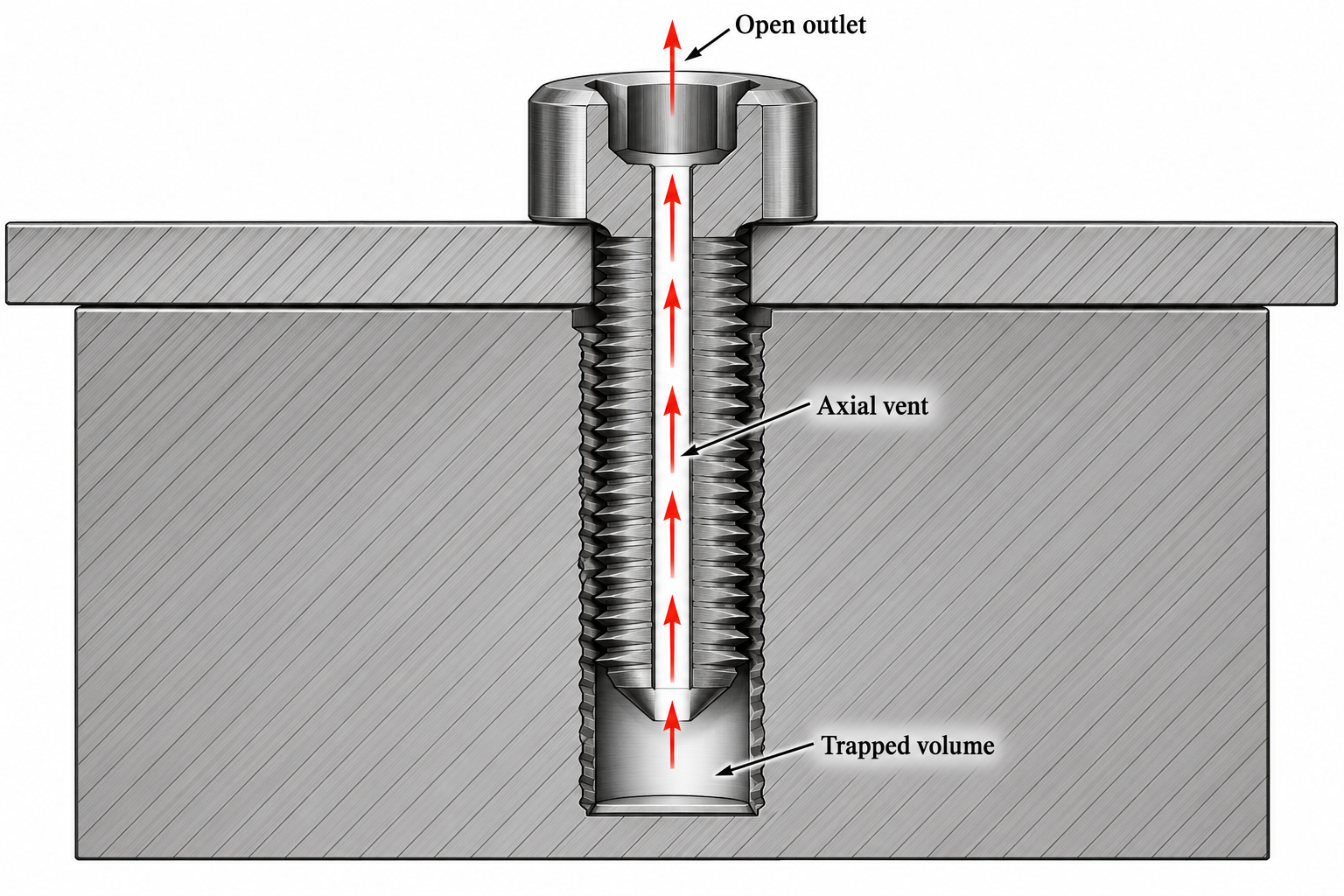
For cable routing, specify the cable envelope, bend restrictions and edge condition rather than only a nominal cable diameter. For a gas passage, evaluate the minimum restriction, path length and outlet. For pressure service, hole continuity is not proof of sealing or pressure capacity; those need a separate design and test specification.
Record bore size, location and accessible internal condition after finishing. An entry plug gauge confirms only what it can physically reach. A functional probe can check passage, but it cannot alone quantify minimum wall. Agree on optical, dimensional or section-based verification appropriate to the part, and identify any destructive qualification samples separately from routine batch checks.
There is no universal percentage. The smooth-section area ratio is 1 − (d/D)², but actual strength also depends on threads, transitions, material condition and loading.
No. It does not establish the bore location along its full length. The drawing and inspection plan must address the critical length and datum relationship.
Do not assume so. Check the reduced section and combined tightening stresses, then validate the assembly with the specified finish and mating components.
Potentially, if passage size, edge treatment, internal finish and assembly motion protect that cable. Electrical or environmental requirements remain part of the equipment design.
Include bore limits, outside geometry, critical minimum wall or geometric controls, material condition, edge requirements, finish, quantity and the intended passage function.
Send the part section, bore function, minimum wall requirement, material condition and inspection criteria. Include the mating components and expected axial, torsional or cyclic loads for a focused manufacturability review.
sst@szsst88.com Attach your drawing in your email app.
2026.10.26
kalyn

 +86 13143444311
 sst@szsst88.com