Tel:
+86 13143444311
Email:sst@szsst88.com
Fax:+0086-755-27322278
Address:Building 9, First Industrial Zone, Tantou Industrial City, Songgang Street, Baoan District, Shenzhen 518105, Guangdong, China
Custom low-profile screws solve a clearance problem only when the head, drive and joint are designed together. Reducing head height can leave less room for tool engagement and load-bearing material. The right specification balances the available space with the clamp load the assembly needs and the torque the finished fastener can safely transmit.
Design takeaway
Define the maximum installed projection first. Then review recess engagement, material around the drive, the bearing surface and installation access. Approve a torque window using the finished screw and representative mating parts.
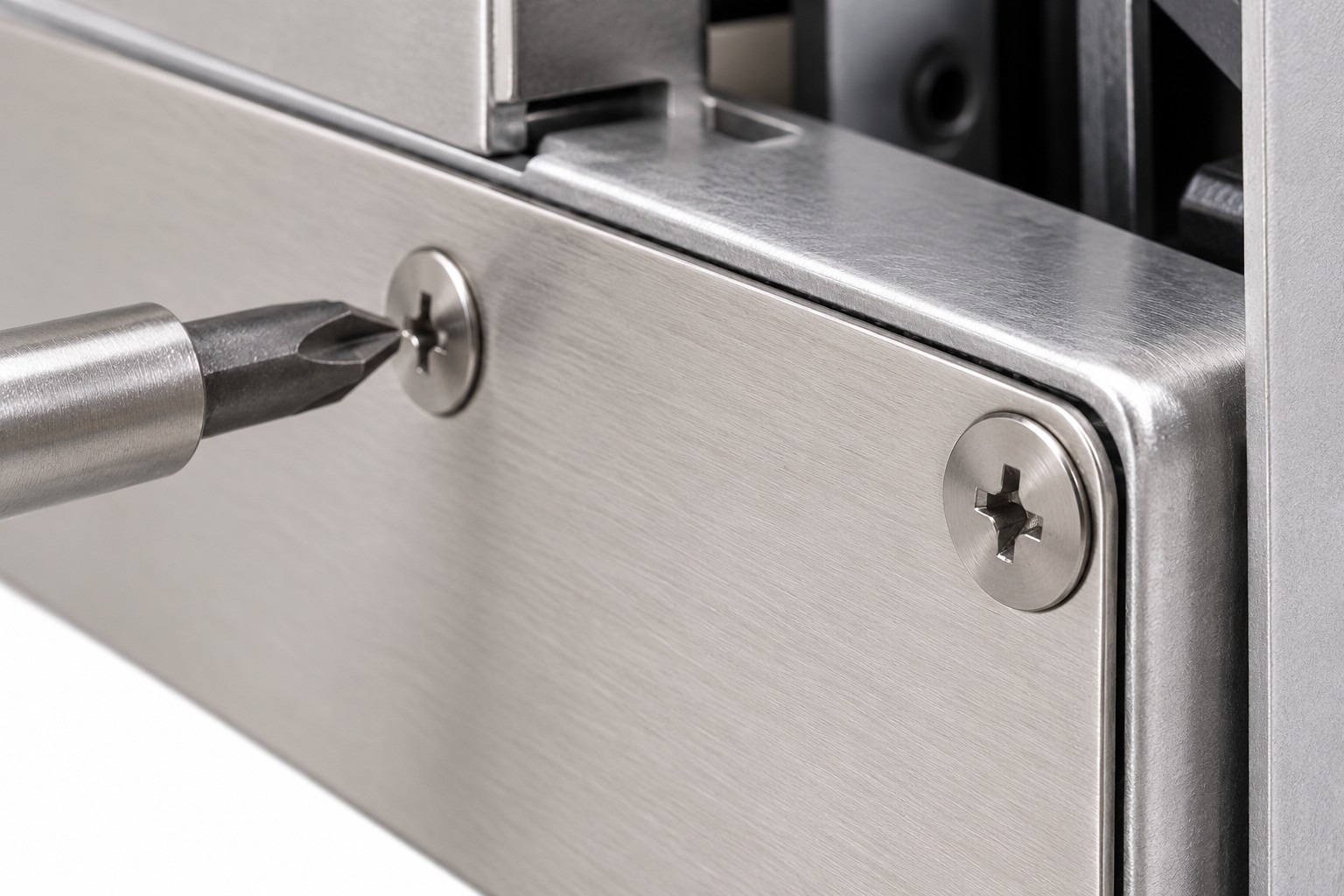
Measure from the installed bearing surface to the nearest obstruction. Include the cover thickness tolerance, coatings, washers if used, and movement of nearby components. A screw that clears a stationary cover may still interfere with a sliding carriage or a cable during operation.
Record the permitted head diameter as well as height. A wider head may help distribute load, but it can conflict with an enclosure edge, a recessed pocket or a nearby connector. Check the driver envelope independently: a shallow head does not make an angled tool engage correctly.
Choose the seat deliberately. A thin head with a flat bearing underside sits above the mating surface. A countersunk head needs a matching conical seat. Removing material for that seat may be unsuitable for a thin cover. These geometries are not interchangeable simply because both offer a low installed profile.
The useful engagement depth is the portion of the recess that properly contacts the bit. Entry chamfers, forming radii, finish buildup and the bit tip can reduce usable contact. Making the recess deeper without reviewing the remaining section below it can create a different weak point.
For highly restricted heads, the best change may be a different drive, a revised head diameter or more tool access. Increasing hardness alone does not resolve every drive or head failure.
Do not transfer a conventional socket-head tightening value to a custom thin head solely because the thread diameter and material grade match. The drive, head, external thread, internal thread and mating surface can impose different limits.
Published data demonstrate why part-specific limits matter: NBK’s SLH low-profile screw catalog provides maximum tightening torques for its defined product geometries and conditions. Those values are not specifications for a different custom screw. Bossard’s customized-geometry calculation guidance also considers bearing geometry, material and friction, and warns about reduced head loadability for certain countersunk fasteners.
If the drive is damaged before the required joint condition is reached, revisit the geometry and process. Simply lowering the torque may leave the assembly insufficiently clamped. Where repeated servicing is expected, include removal and reinstallation in the validation plan.
| Assembly | Pain point | What to review |
|---|---|---|
| Machine-vision or sensor housing | Head projection interferes with surrounding equipment; the bit approaches at an angle. | Installed height, connector clearance and straight tool access. |
| Robot gripper cover | A moving finger or slide passes close to the cover fastener. | Full motion envelope, cover tolerance and retention under the actual duty cycle. |
| Thin equipment enclosure | The panel distorts under the head or lacks thickness for a countersink. | Bearing footprint, hole geometry, support stiffness and clamp load. |
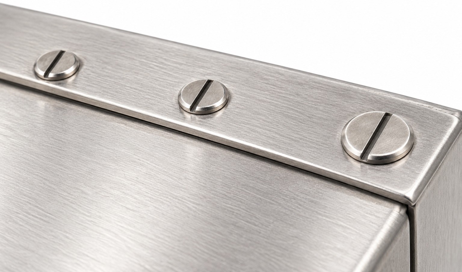
These are design situations to evaluate, rather than a single universal fastener specification. For available starting geometries, see our ultra-thin head screw product page and low-head slotted fastening options.
A useful RFQ specifies more than a reduced head height. Provide the following so manufacturing feasibility and assembly performance can be reviewed together:
Discuss forming feasibility and any necessary secondary operations before releasing tooling. Tight tolerances should be assigned to functional dimensions, with an agreed way to inspect them. A change to the recess, coating or mating seat should trigger a review of the installation validation.
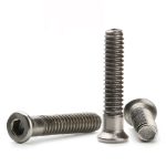
A flat undercut screw has a countersunk head with a reduced head depth compared with the corresponding conventional form. It still requires a compatible seat. It is different from a thin head with a flat bearing underside, which rests on the surface. Check the selected product drawing before substituting one for the other.
“Thinnest” can mean the smallest thread diameter or the lowest head height. Those are separate dimensions, and there is no single minimum applicable to every material, drive and load requirement. For a clearance problem, specify the maximum installed head projection and retain the thread size needed by the joint.
Do not assume so. Reduced head or drive geometry may limit capacity before the threaded shank does. Use the specification for the exact product, or establish a validated installation window for the custom geometry, finish and mating joint.
Possible causes include insufficient bit engagement, a worn or mismatched bit, angled installation, finish obstructing the recess, or torque beyond the drive capacity. Inspect the damaged parts and installation process before changing the thread or material.
Only after reviewing the remaining head section, drive engagement, bearing contact and required clamp load. If the reduced geometry cannot support the requirement, the seat, drive, tool access or surrounding clearance may need to change.
Send Shi Shi Tong the screw drawing, mating-section drawing, clearance limit, material and finish requirements, installation method and quantities. Include the failure symptom if an existing fastener is damaging the recess or cover.
Send drawings for engineering review | Explore custom special screw configurations
2026.10.21
kalyn

 +86 13143444311
 sst@szsst88.com