
 +86 13143444311
 sst@szsst88.com
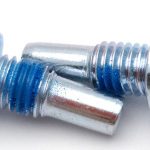
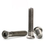
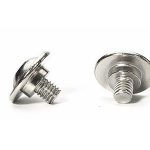

ALD sample holder screws must maintain the intended clamping relationship while allowing the assembly’s designed thermal movement. Where a screw enters a blind hole, assess the trapped pocket and its escape route separately. A vent bore does not resolve an overconstrained fixture, and additional tightening does not correct a blocked gas path.
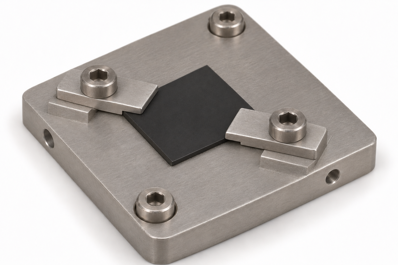
Separate locating from clamping
A sample holder may need to establish a repeatable reference position, resist transfer loads and keep the specimen in contact with a support. Those functions should be assigned deliberately. If every fastener is treated as a tight locator, differential expansion can introduce forces that the clamp design did not intend.
Identify the primary datum, the feature that prevents unwanted rotation and any direction in which the sample or holder must move. A slot, flexure or controlled clearance may provide that movement when designed into the fixture. Do not enlarge holes or loosen screws as an improvised thermal accommodation.
For an edge clamp, show the contact point on the sample, the support beneath the clamp and the screw bearing face. Check that the screw tightens the intended interface instead of stopping on a shoulder, thread runout or hole bottom. The sample’s allowable contact load is a separate input from the screw’s strength.
Review blind holes and connected pockets
Temporal ALD exposes the substrate to alternating precursor steps with separation between them. Beneq’s ALD overview explains the sequential surface-reaction principle. This makes the geometry of restricted internal pockets worth reviewing, but it does not establish that a particular screw causes a measured process deviation.
On an assembly section, mark the volume below each screw tip and determine whether it connects to the chamber. If an axial vent is selected, trace its inlet, bore and head outlet. A vented screw may open the tip pocket while leaving another pocket under a broad washer unconnected.
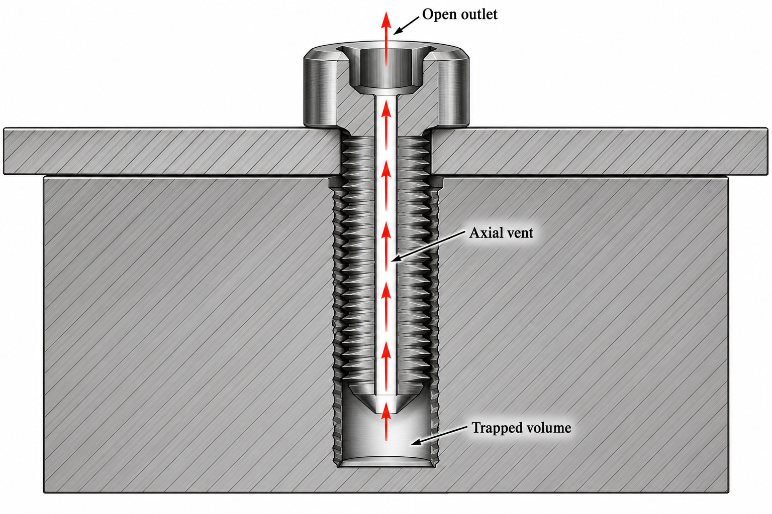
Do not infer a required bore diameter or purge-time reduction from the presence of a visible hole. The equipment owner evaluates flow and process behavior. The fastener review establishes the specified passage geometry, continuity and remaining mechanical section.
Define the thermal envelope at the fixture
Specify the starting temperature, local operating range, dwell time and number of expected cycles. Record whether the holder and screw reach the same temperature or experience different heating paths. A substrate setpoint is not automatically the screw temperature.
The Lesker ALD150-LX datasheet lists distinct heating specifications for the substrate, chamber and delivery components. The engineering consequence is to obtain local conditions rather than assign one process number to every fastener. These equipment specifications are not temperature ratings for Shi Shi Tong screws.
At higher temperatures, assess the approved material’s strength and time-dependent behavior as well as expansion. A fixture can retain its dimensions after cooling while experiencing an unacceptable clamp load during the hot part of the cycle.
Calculate expansion before fixing the geometry
The TIMETAL 50A datasheet gives a mean linear expansion coefficient of 8.6 × 10⁻⁶/°C over 20–100°C and 9.5 × 10⁻⁶/°C over 20–300°C. Retain the temperature interval when using a coefficient. A single room-temperature number should not be extrapolated across every ALD cycle.
For a selected 50 mm titanium reference length heated uniformly from 20 to 100°C:
ΔL = αLΔT = 8.6 × 10−6 × 50 × 80 = 0.0344 mm.
The selected length and temperature interval illustrate free expansion, not an ALD operating recommendation or measured fixture displacement.
The 34.4 µm result matters when a fixture’s allowed movement is of similar magnitude. It is not the differential movement between two different materials. For that comparison, calculate each component’s expansion over its own relevant length and temperature range, then apply the actual constraint scheme.
If a screw and a clamped stack are mechanically restrained, free expansion is only an input to the joint model. Clamp-load change also depends on their stiffnesses, temperature differences, contact behavior and any plastic or time-dependent deformation. Do not convert free expansion directly into a torque correction.
Check the assembly at temperature
| Observed concern | Geometry or evidence to check | What not to assume |
|---|---|---|
| The holder shifts after heating | Datum scheme, intended sliding direction, contact marks and local temperatures | That a stronger screw alone restores repeatable location |
| The sample is overstressed or loses contact | Clamp lever arm, support height, thermal movement and permitted contact load | That one room-temperature torque guarantees the hot clamp force |
| The screw seats but the clamp remains loose | Bottoming, shoulder contact, thread runout and bearing surfaces | That increasing torque will close the correct interface |
| The fixture has a restricted internal pocket | Connected route through the installed screw and surrounding parts | That a bore in the loose screw verifies the complete assembly |
Inspect hardware only after the equipment has been isolated, vented and cooled under its approved procedure. Keep operational observations separate from disassembly evidence. Record the position of the affected screw and the assembly revision before replacing parts.
Specify functional acceptance
The drawing should distinguish tolerances that establish sample location from those that provide clearance. Mark the head-bearing surface, full-thread interval, permitted tip clearance and vent outlet. If a bore is required, define its position and minimum remaining wall as well as diameter.
For custom titanium screws for sample fixtures, provide the approved material specification and service envelope alongside the geometry. Agree which component measurements the supplier reports and which assembly or equipment trials the customer performs.
Release a replacement only after checking mechanical fit, the intended hot and cold movement, and the gas path where applicable. Keep the approved drawing and test configuration with the purchasing record so that the next batch is evaluated against the same functional conditions.
Technical FAQ
Do all ALD sample holders need vented screws?
No. Review whether the particular fastening interface creates a restricted internal volume. The presence of ALD equipment alone does not determine every screw feature.
Does a vented screw shorten the ALD purge step?
Not by a guaranteed amount. A vent can provide a route from a trapped pocket, but the equipment owner must assess the complete flow and process response.
Can tightening torque compensate for thermal expansion?
Torque is not a substitute for the thermal and stiffness model. The design must maintain the required contact load while allowing intended movement.
Which expansion coefficient should be used?
Use data for the approved material and relevant temperature interval. Check whether the screw and mating part share the same temperature history before comparing their movements.
What is the difference between a locating screw and a clamping screw?
Locating features establish position; clamping features retain contact or resist separation. One component may perform both roles only when the geometry and tolerance scheme are designed for both.
Review the screw and the mating assembly together
Send your screw drawing, a section through the mating hole, material specification, quantity and critical acceptance requirements. Shi Shi Tong reviews the geometry, manufacturing route and inspection requirements before confirming a custom screw proposal.
Copy this email address and attach your drawings in your email service:sst@szsst88.comOpen Email App →
If your email app does not open, copy this address into your email service.