
 +86 13143444311
 sst@szsst88.com
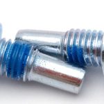
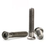

Material loss on a titanium screw head in plasma equipment needs a location-based investigation. Compare the exposed face, protected surfaces and drive recess before deciding whether the cause is process exposure, tool damage or an earlier manufacturing defect. A surface appearance alone cannot establish the mechanism or the remaining load capacity.
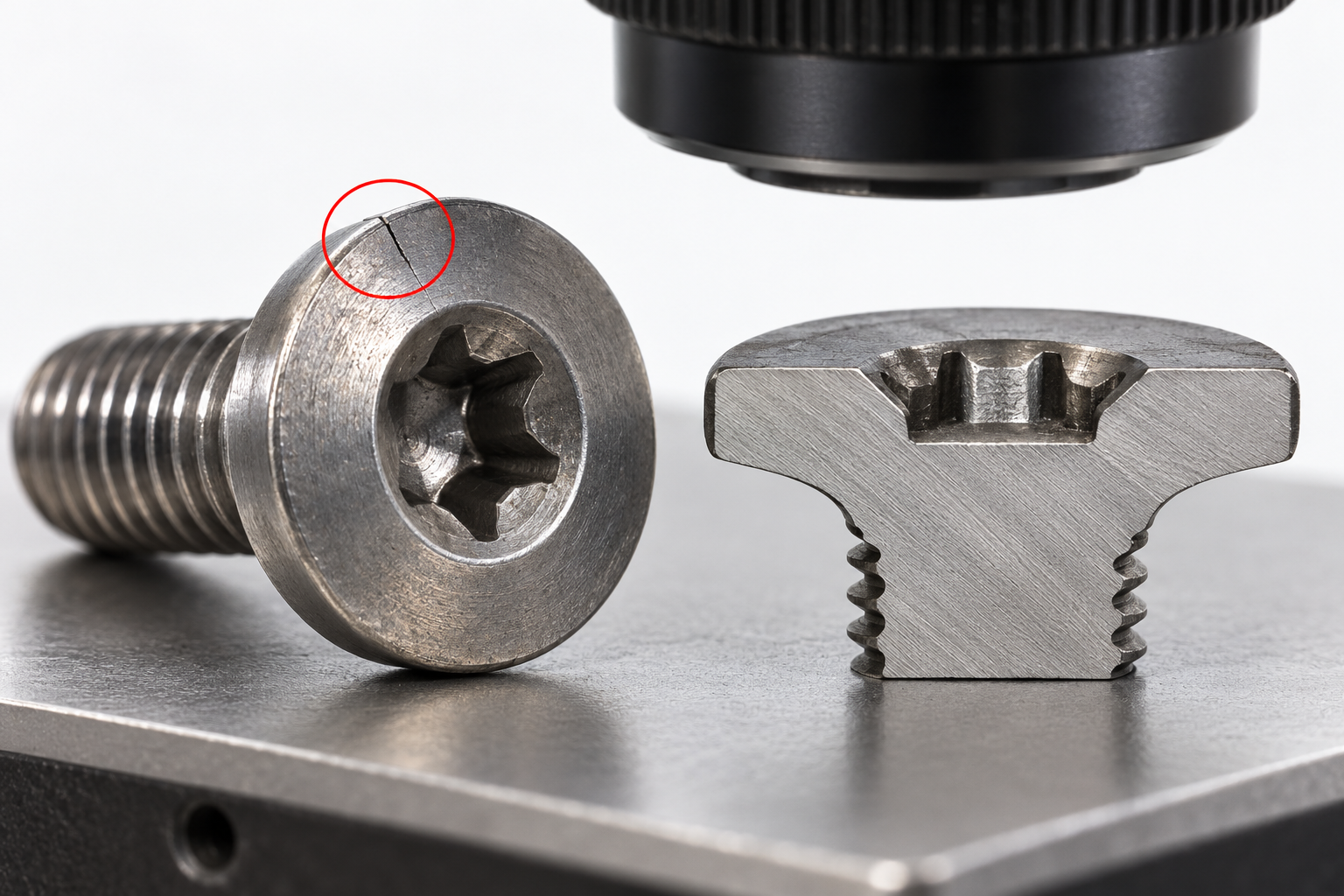
Record the damage before changing parts
First identify the screw position, drawing revision, material evidence, installation history and equipment cycles associated with it. Photograph the head before removal where safe access permits. After removal, keep its orientation and location traceable. A collection of unidentified damaged screws is much less useful than a smaller set linked to specific positions.
Perform inspection only after the equipment has been isolated, vented and made safe under the equipment owner’s procedure. Where a screw no longer meets the assembly’s acceptance requirement, remove the affected hardware from service for engineering assessment rather than repeatedly tightening it.
Distinguish changed geometry from changed appearance. Color, roughness, loss of a sharp edge and a fractured piece are different observations. Describe what can be measured before assigning words such as corrosion, erosion or fatigue.
Separate possible damage mechanisms
Oxford Instruments describes reactive ion etching as involving physical and chemical effects. Its ion-beam etching explanation also distinguishes inert-ion milling from processes with a reactive contribution. These mechanisms explain why ordinary room-temperature chemical-resistance data cannot validate every exposed screw location.
| Possible mechanism | Evidence worth collecting | What the observation cannot prove alone |
|---|---|---|
| Physical removal during exposure | Changes correlated with exposure direction and protected areas | An erosion rate or service life without quantified exposure history |
| Chemical or ion-assisted attack | Local process conditions, surface analysis and comparison material evidence | Compatibility from the feed-gas name alone |
| Driver damage during assembly or removal | Directional marks inside the recess, bit fit, tool condition and removal record | That all external surface change came from the driver |
| Pre-existing head defect or mechanical crack | Unexposed reference parts, fracture examination and manufacturing records | That a crack seen after service necessarily started in service |
Several mechanisms can occur on the same part. A worn recess may be damaged further during removal; a locally thinned region may then fracture mechanically. Keep the sequence of events separate from the final appearance.
Compare exposed and protected surfaces
Map the face directed toward the process, the underside of the head, the recess walls and any shielded region. Compare screws from different positions only when their material, geometry and service history are known. Different positions may experience different temperatures, energetic-particle exposure or electrical conditions.
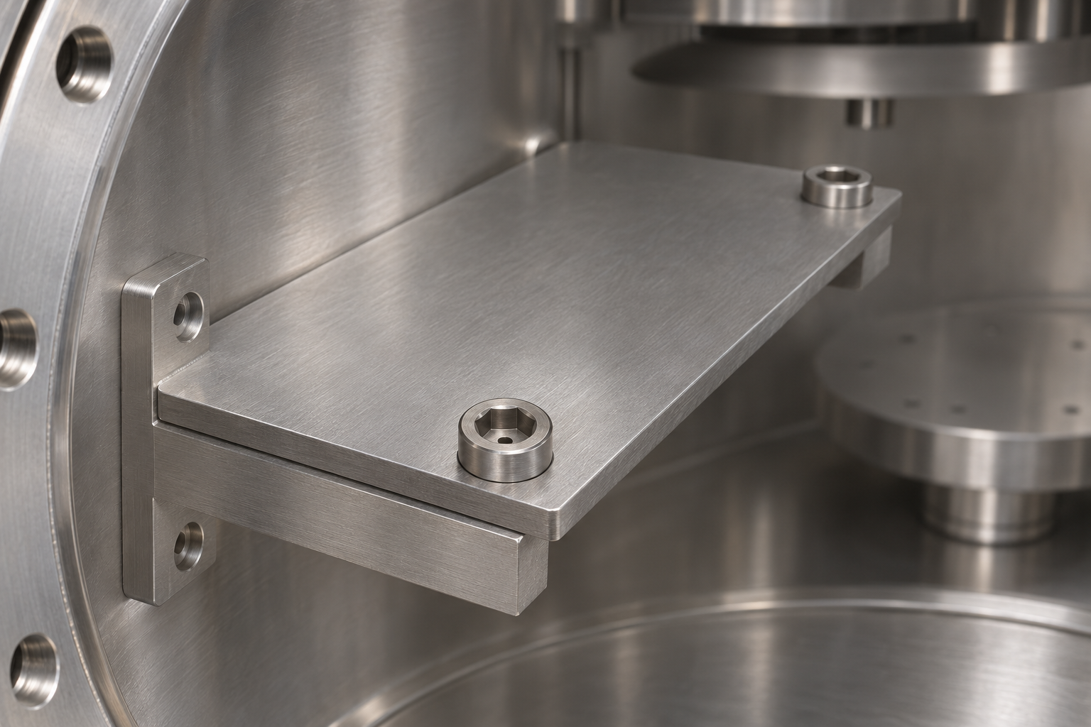
Shielding can change line-of-sight exposure, but it does not prove that reactive species cannot reach the joint. A plasma-etching review from the University of Houston describes how physical, chemical and ion-enhanced contributions depend on the material system and incident species. Apply that distinction when planning an investigation, not as a prediction of a specific screw’s wear rate.
Ask the equipment owner for the relevant local conditions and any approved material restrictions. Do not change bias, gas or process settings as a fastener troubleshooting shortcut. Those changes belong to the equipment’s controlled engineering process.
Assess the remaining functional section
Measure the geometry that performs the function: head height, bearing diameter, recess engagement and the ligament between the recess and loaded surfaces. If the screw is vented, include the bore position and remaining wall. A good external thread gauge result does not establish an intact head.
A dimensional change must be compared with measurement uncertainty. Suppose a selected before/after comparison gives 4.00 mm and 3.96 mm head height. The apparent change is 0.04 mm. If each reading has a bounded uncertainty of ±0.02 mm, a conservative difference interval is 0.00–0.08 mm.
Those selected readings illustrate the measurement problem, not a customer result. A finer method or a better-controlled datum may be needed before asserting a 0.04 mm loss.
For a nonuniform profile, measuring the highest point can miss a local thin region. Select the inspection method and sampling locations around the suspected damage. A sectioned part is useful when the inner geometry matters, but that part is consumed by the examination and cannot return to service.
Do not convert a percentage of lost head height into the same percentage of lost strength. The loaded geometry, recess shape, stress concentration and damage mechanism determine the effect. Agree a functional rejection criterion with the responsible engineer rather than inventing a universal wear allowance.
Control the replacement decision
A direct replacement should preserve the approved material, geometry and condition unless the engineering review authorizes a change. A different titanium grade, a thicker head or an added coating can affect fit, installation, electrical behavior and process interaction.
First establish whether the original fastener met its purchasing requirements. Then decide whether the problem is a manufacturing nonconformance, a design limitation or a service condition outside the approved envelope. This distinction determines whether to correct a batch, revise a drawing or review equipment-side exposure.
For custom titanium screw manufacturing, provide the damaged-part evidence and the approved drawing together. The supplier can review geometry and manufacturing controls while the equipment owner evaluates the actual plasma-service compatibility.
Define acceptance for the next batch
Record the starting head geometry, recess profile, material condition and any critical minimum section. Specify how each feature is measured and what evidence accompanies the batch. Preserve an unexposed reference where the investigation plan requires a comparison.
If a design change is approved, use an agreed equipment evaluation with the revision, position and service history recorded. Define the inspection interval and decision criteria from that evaluation. Do not claim a fixed service life from a material name or one successful short run.
Technical FAQ
Does titanium corrosion resistance guarantee plasma resistance?
No. Plasma exposure can involve physical removal and reactive species as well as temperature effects. Suitability must be established for the actual equipment position and service conditions.
Can a discolored head be rejected as eroded?
Discoloration alone does not quantify material loss. Compare geometry, surface condition and the agreed acceptance criteria before assigning a cause.
How long do titanium screws last in plasma equipment?
There is no universal interval. The material, geometry, local exposure, loading and inspection criteria determine the service plan. Use equipment-specific evidence rather than an unsupported lifetime claim.
Will a thicker head solve the problem?
It may change the remaining section, but it can also affect clearance, exposure and assembly. Establish the damage mechanism and approve the revised joint before substitution.
What evidence helps a supplier investigate head damage?
Provide before/after images where available, screw position, drawing revision, material records, measured changes, installation/removal history and the equipment-approved service envelope.
Review the screw and the mating assembly together
Send your screw drawing, a section through the mating hole, material specification, quantity and critical acceptance requirements. Shi Shi Tong reviews the geometry, manufacturing route and inspection requirements before confirming a custom screw proposal.
Copy this email address and attach your drawings in your email service:sst@szsst88.comOpen Email App →
If your email app does not open, copy this address into your email service.