Tel:
+86 13143444311
Email:sst@szsst88.com
Fax:+0086-755-27322278
Address:Building 9, First Industrial Zone, Tantou Industrial City, Songgang Street, Baoan District, Shenzhen 518105, Guangdong, China
Vented screw design starts with a continuous path from a trapped cavity to the evacuated space. A drilled hole helps only when it communicates with the actual pocket and remains open after installation. Bore diameter, outlet position, machining residue and the surrounding assembly all matter. A vent feature alone does not establish vacuum cleanliness, leak tightness or a specified pump-down time.
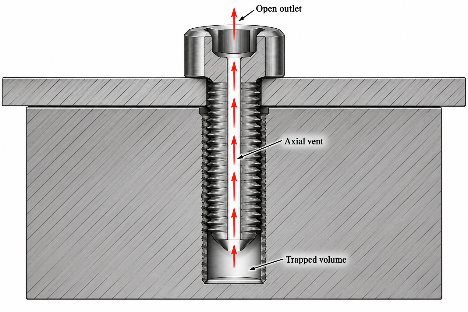
A screw installed in a blind tapped hole can leave a pocket beneath its tip. Gas can escape slowly through restrictive clearances around the threads. An axial bore provides a more direct connection, provided the bore reaches the pocket and the head outlet is exposed to the same evacuated chamber. It is not a substitute for sealing a pressure boundary.
Start with a section of the complete assembly. Mark each enclosed space, including those under washers, within counterbores and between clamped components. One axial hole does not necessarily vent all these pockets. Where a side passage is used, its position must remain clear of the mating thread, washer and clamped plate throughout the tolerance range.
The UC Components vented-fastener guide describes the trapped-gas problem. Geometry selection and cleanliness requirements still belong to the particular assembly.
For a straight circular tube in the molecular-flow limit, Leybold gives the air-at-20°C relation C = 12.1 d³/L, with C in litres per second and both d and L in centimetres. Its stated long-tube condition is L ≥ 10d, with d·p below 10⁻² mbar·cm. This is a useful screening relation for an open bore, not a complete chamber evacuation model.
| Bore diameter | Bore length | Calculated C |
|---|---|---|
| 1.0 mm (0.10 cm) | 20 mm (2.0 cm) | 0.00605 L/s |
| 1.5 mm (0.15 cm) | 20 mm (2.0 cm) | 0.02042 L/s |
| 1.0 mm (0.10 cm) | 40 mm (4.0 cm) | 0.00303 L/s |
Under these conditions, increasing diameter from 1.0 to 1.5 mm multiplies bore conductance by 3.375; doubling length halves it. The result does not mean the entire chamber pumps down 3.375 times faster. Other restrictions, surface gas release, chamber volume and pump speed can dominate. Short passages, entrance losses and other gases require the appropriate model. Source: Leybold conductance equations and applicability limits.
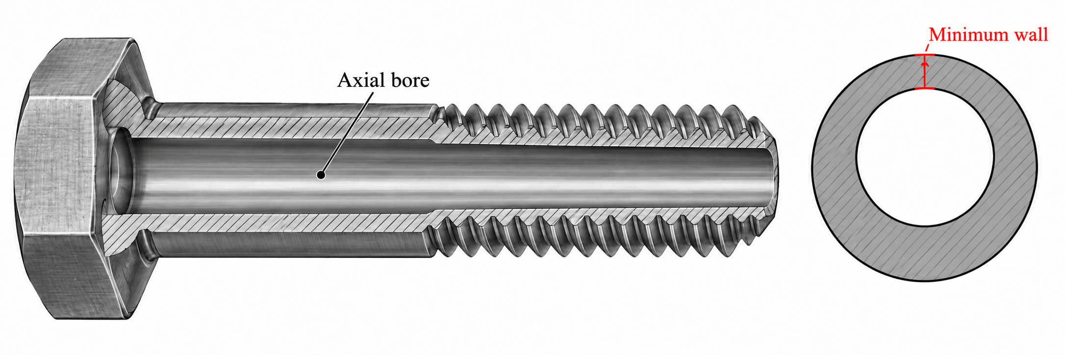
A larger bore can improve conductance while reducing the remaining section. For a smooth circular section, the remaining area is A = π(D² − d²)/4. At a 4.0 mm outside diameter, a 1.0 mm bore leaves 11.78 mm²; a 1.5 mm bore leaves 10.80 mm². That is about 8.3% less area than the smaller-bore version at the same section.
A threaded fastener must also be checked at the thread-root region, head-to-shank transition and any intersecting holes. A smooth-annulus calculation does not include thread stress concentration, combined tightening stress or fatigue. Do not apply an unmodified solid-screw torque table to a vented version merely because its nominal thread designation is unchanged.
| Location | Potential obstruction | Drawing or process action |
|---|---|---|
| Head outlet | Plug, cover, driver debris or adhesive | Show the outlet in the final installed condition |
| Tip inlet | Bottom contact or compacted chips | Specify clearance and verify an open inlet |
| Cross-drilled passage | Thread engagement or washer overlap | Dimension location from an assembly datum |
| Internal bore | Burrs, oil or retained abrasive | Define deburring and cleanliness acceptance |
In vacuum instrumentation or a chamber-mounted fixture, an accessible outlet is valuable only if the fastening location belongs inside the evacuated volume. If a hole could connect atmosphere to vacuum across a sealing boundary, the design needs a separate sealing review. For contamination-sensitive equipment, specify allowed residues, cleaning, packaging and verification with the system owner; the term “vented” does not define any of them.
Specify bore diameter, minimum open length, outlet location and the surfaces used to locate the passage. An entry diameter check cannot establish that a long hole is unobstructed throughout. Depending on geometry, inspection may combine a suitable probe, optical examination, a defined flow check or sectioning during process qualification. Agree on the method before production.
Inspect after the final relevant process. Deburring, coating and cleaning can change the passage condition. Keep bore-patency results separate from thread-gauge acceptance and separate again from vacuum performance of the assembled equipment. SHISHITONG can review manufacturability of the custom fastener; application-specific vacuum acceptance requires the agreed system-level criteria.
It is a fastener with a passage intended to let gas escape from otherwise restricted spaces, commonly a blind-hole pocket. The passage must connect that space to an open outlet.
No. Evaluate trapped volume, available escape paths and evacuation requirements. A through-hole or another open path may already address the pocket.
It can increase conductance, but also removes material and may complicate drilling, deburring and inspection. Optimize flow and mechanical requirements together.
No. Material, surface condition, cleaning, packaging and assembled performance all require application-specific acceptance.
Yes, if it migrates into an inlet or outlet. Review the locking method, application location and chemical compatibility with the vacuum requirements.
Send the screw and assembly sections, bore requirement, material, operating temperature, vacuum conditions and cleanliness specification. Include the required inspection method and order quantity so the geometry and process can be reviewed together.
sst@szsst88.com Attach your drawing in your email app.
2026.10.25
kalyn

 +86 13143444311
 sst@szsst88.com