Tel:
+86 13143444311
Email:sst@szsst88.com
Fax:+0086-755-27322278
Address:Building 9, First Industrial Zone, Tantou Industrial City, Songgang Street, Baoan District, Shenzhen 518105, Guangdong, China
A custom security screw drive should discourage unwanted access while allowing the planned installation and maintenance process. Recess shape is only one part of that decision. Driver reach, centre-pin clearance, recess depth, head wall thickness and tool availability determine whether the authorized technician can actually service the equipment.
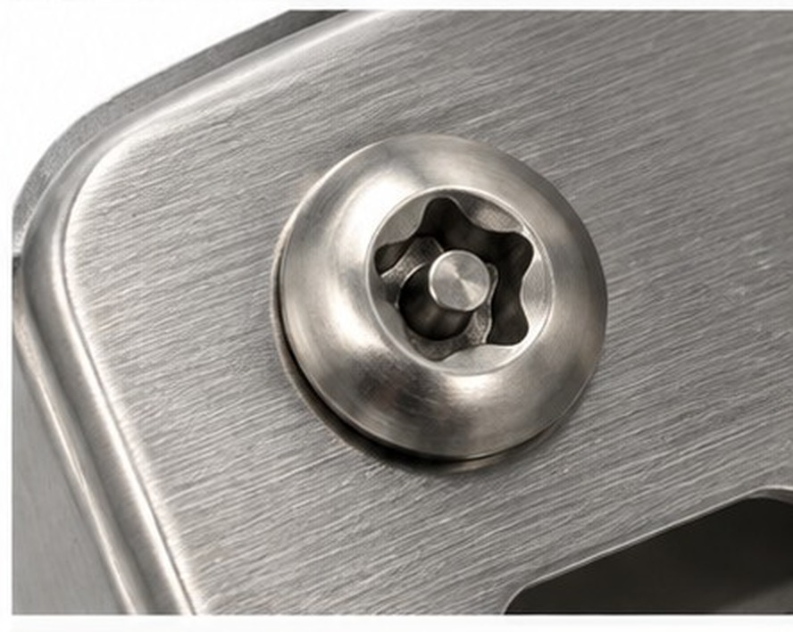
An outdoor access panel opened every month has different requirements from a cover intended to remain closed throughout its life. Start by stating who may open it, with what tool, how often, and whether removal must be reversible. A more unusual drive can complicate field maintenance without necessarily adding useful protection.
| Drive approach | Service implication | Design question |
|---|---|---|
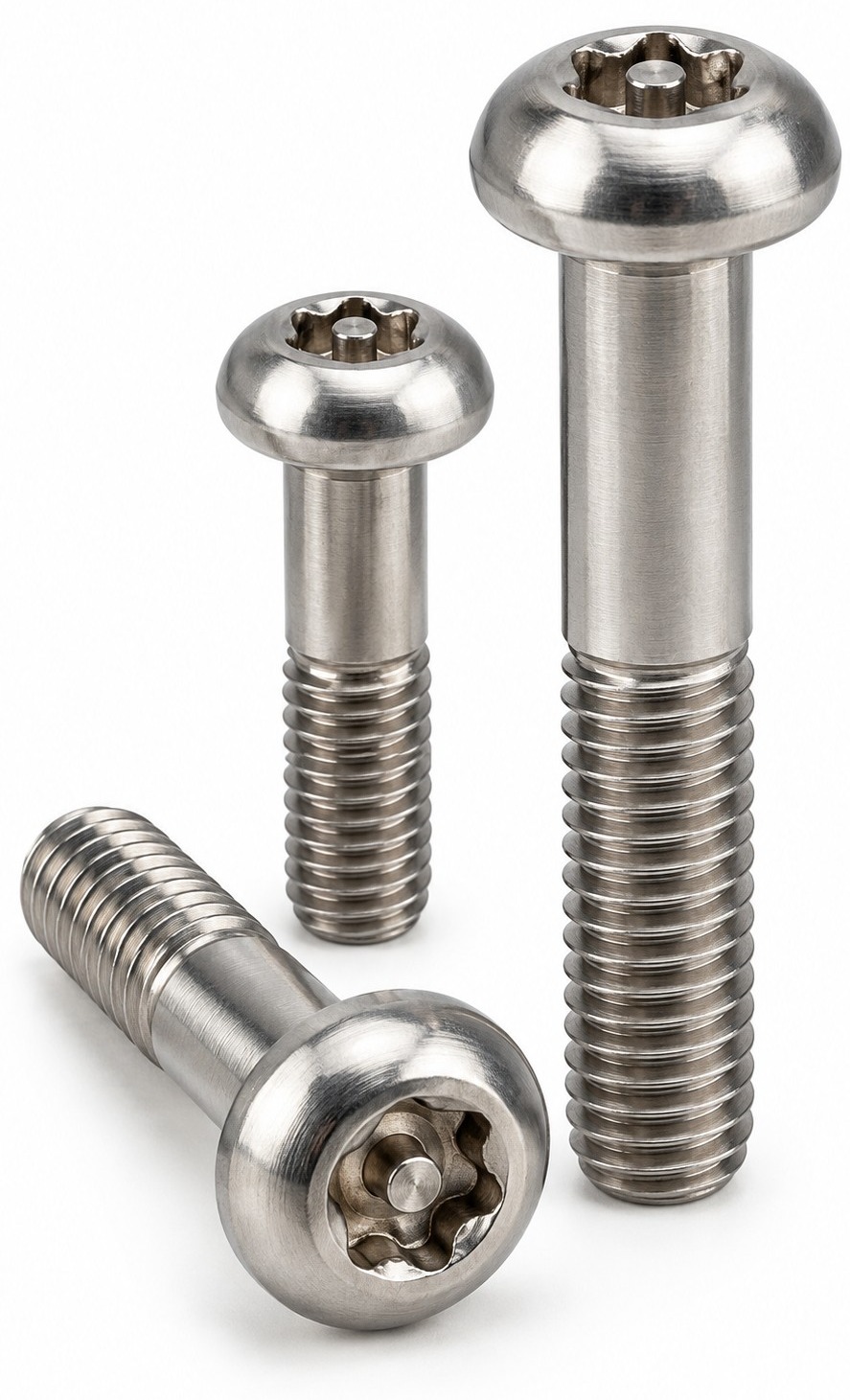
| Pin-in recessed drive | Needs the matching hollow-centre bit | Can the bit clear the pin and fully engage? |
| Two-hole drive | Needs compatible pin spacing and engagement | Is there enough head material around each hole? |
| One-way drive | Ordinary reverse driving is restricted | Is the approved removal method acceptable? |
| Special external profile | Needs a matching socket or tool | Can the socket enter the surrounding recess? |
Treat tamper resistance as a defined requirement, not a guarantee of being impossible to remove. Standardized commercial security bits may be readily available. For controlled access, tool management and enclosure design can be as important as the screw profile. Our custom security fastener range provides a starting point for discussing geometry.
Do not size an access opening from the bit tip alone. The bit holder or socket may be larger and may contact the enclosure before the tip reaches the recess. Include approach angle, axial reach and the space needed to keep the driver aligned.
| Specified geometry | Calculation | Result |
|---|---|---|
| Access opening minimum: 7.80 mm; tool envelope maximum: 7.20 mm | Radial clearance = (7.80 − 7.20)/2 | 0.30 mm |
| Required lateral positioning allowance: 0.25 mm | Remaining geometric margin = 0.30 − 0.25 | 0.05 mm |
This stated geometry illustrates a tight access condition; it is not a recommended clearance. It excludes tool tilt, runout, burrs and coating buildup. A small positive static margin can disappear during real service. Check the tool and enclosure together rather than approving the screw from its drawing alone.
A central pin can prevent a solid bit from entering, but excessive pin height or insufficient depth in the correct bit can also stop that bit from seating. The tool may appear engaged while only its tip contacts the drive. Specify the matching tool geometry and verify contact at the intended depth.
For a low head, increasing recess depth removes material beneath the recess; increasing recess width reduces the surrounding wall. A custom drive therefore needs a head-strength and torque review. Surface treatment can also alter effective fit. Inspect and test the finished part rather than using an unfinished sample as the only acceptance reference.
For a public-facing electronics enclosure, consider corrosion products, dirt accumulation and access with the equipment installed. For a recessed instrument panel, check whether cables or neighbouring components block a straight tool path. For an outdoor cover, a drive that works on a clean bench may be difficult to engage after exposure.
Define what happens when the screw is damaged or the specified tool is unavailable. This belongs in the service plan before release. A one-way design may be unsuitable when frequent reversible maintenance is required. Conversely, a removable pin-in drive should not be described as permanent merely because a normal bit does not fit.
| Acceptance item | Evidence to retain |
|---|---|
| Drive geometry | Matched gauges or agreed dimensional checks |
| Tool access | Installation with the specified bit and holder in the actual envelope |
| Torque transmission | Approved tightening conditions and condition after tightening |
| Service cycling | Removal and reinstallation results for the required cycle count |
| Finish condition | Fit and corrosion-related service checks where specified |
Keep recess acceptance separate from thread acceptance. A screw can pass a thread gauge and still reject the intended driver. Record the tool identifier, screw revision and finish used for the trial. Do not claim a numerical torque capacity until it has been established for the selected geometry and material condition.
Common approaches include pin-in recessed drives, two-hole drives, one-way profiles and special external profiles. Choose according to the intended service and access requirement.
A pin-in security version has a centre pin requiring a compatible hollow-centre bit. Standard and security profiles must be identified correctly; a similar appearance does not prove tool compatibility.
Common families include slotted, cross-recessed, hex socket, hexalobular and external wrenching profiles. Security variants add features or specialized geometries to restrict ordinary tool access.
No. Their effect depends on the drive, available tools, access and the complete enclosure. Specify the intended resistance and maintenance requirements rather than an absolute promise.
Possibly, but usable recess depth, surrounding wall and material beneath the recess must be reviewed together. Confirm tool fit and torque performance with the finished design.
Drive reference: Accu screw-drive identification sheet. Exact dimensional and service requirements should be placed on the custom drawing.
Send the head envelope, preferred drive, required torque, access-opening dimensions and maintenance cycle. Include the intended bit or tool drawing so screw and service access can be reviewed together.
sst@szsst88.com Attach your drawing in your email app.
2026.10.29
kalyn

 +86 13143444311
 sst@szsst88.com