
 +86 13143444311
 sst@szsst88.com

Custom fastener engineering · Assembly troubleshooting
A slipping driver can leave a panel loose while damaging a screw that is difficult to replace. This guide helps manufacturing engineers, quality teams and OEM buyers identify whether the problem lies in the bit, the recess or the assembly process.
If a hex bit slips before the required assembly torque is reached, first compare a verified new bit with the used bit under the same conditions. Check drive size, seating, alignment and the tightening program before changing recess depth or material hardness. If the new bit also slips, investigate the finished recess geometry and the torque demand of the joint.
Use separate, undamaged screws from the same lot for each condition. Reusing a rounded socket can make a good bit appear defective. Keep the joint stack, surface condition, tool station, speed and axial force consistent. Record the number of failures against the number of installations, where slipping starts, and whether the panel actually seats.
A short comparison is a screening test, not a production acceptance plan. If a new bit works, it points toward tooling wear or fit; it does not prove that the recess is within specification. A new bit can temporarily compensate for a marginal socket.
Separate socket rounding from other assembly failures
Hex socket screw stripping means the internal drive profile has lost its ability to transmit torque. It should be distinguished from thread stripping, a slipping tool clutch and axial disengagement of the bit. These failures need different corrective actions.
| Observation | First checks | Interpretation |
|---|---|---|
| Used bit slips; new bit performs better | Bit profile, wear, size and station repeatability | Tooling contributes; still verify the recess dimensions. |
| Both bits rock or seat incompletely | Drive size, coating, debris, entry geometry and effective engagement | Fit or seating may be limiting torque transfer. |
| Problem occurs at one station only | Alignment, axial force, speed, calibration and shutoff behavior | Investigate the assembly process before redesigning the screw. |
| Socket walls deform or corners fracture | Geometry, applied torque, material condition and hardness | Appearance guides the investigation; it does not identify a single cause. |
| Screw rotates but the joint does not tighten | Male and female threads, bottoming and joint stack | The failure may be outside the drive recess. |
In a sensor housing, a driver may approach at an angle because adjacent components restrict access. In a robotic end effector, repeated maintenance can accumulate drive damage. In a control panel, resistance from a misaligned hole or incorrect screw length can raise torque before the panel seats. Diagnose the assembly as well as the screw.
Check metric and inch tooling before measuring wear
For equipment assembled or serviced across the United States and Europe, identify the actual drive specification. An M4 thread designation does not by itself define the socket size of a custom screw. Likewise, an inch thread does not justify selecting a visually similar metric bit.
A 1/8-inch hex bit is 3.175 mm across flats. It is not interchangeable with a 3.00 mm bit. Keep thread size, drive size and the units used for each in separate drawing fields. Use the specified tip profile for the tightening operation; do not substitute a ball-end tool without validating its permitted torque and access angle.
How bit wear changes clearance
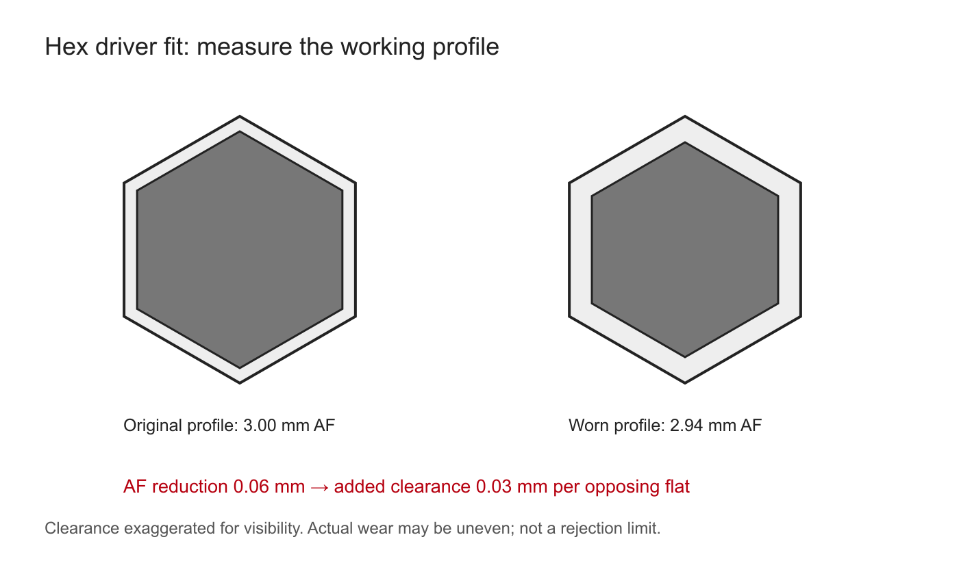
For a centered, idealized hex bit in an unchanged socket, the increase in clearance at each opposing flat is:
Additional clearance per flat = (original bit AF − worn bit AF) / 2
A reduction from 3.00 mm to 2.94 mm across flats increases this clearance by 0.03 mm per flat, or approximately 0.00118 inch. That is a geometric calculation, not a universal rejection limit. Actual wear can be uneven; damaged corners and the tool profile also affect contact.
Set the replacement limit using the approved bit specification and installation trials. Do not treat 2.94 mm, 2.98 mm or any other isolated measurement as a universal maintenance threshold. Wera’s explanation of hex drive contact geometry shows why contact location matters when a recess rounds out; it does not establish a torque rating for a custom screw.
Specify effective engagement separately from total depth
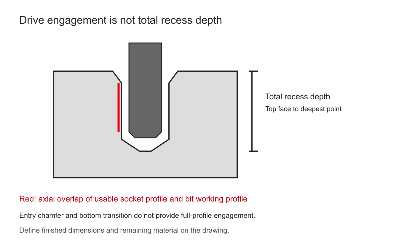
Total recess depth is not the same as usable drive engagement. The entry chamfer, bottom transition, recess taper and bit tip geometry can prevent part of the cavity from carrying torque effectively.
- Total recess depth: distance from the explicitly identified reference plane to the deepest point of the cavity.
- Effective drive depth: the axial region meeting the specified functional drive profile and dimensional requirements.
- Actual engagement length: the overlap between that usable region and the seated bit’s working profile.
A note reading “recess depth 3 mm” leaves both the reference plane and the functional requirement open to interpretation. Identify the head top face or another agreed datum on the section drawing. If the underhead bearing face is used to locate the recess, define the coordinate direction and endpoints explicitly; that coordinate must not be confused with insertion depth.
First inspect for contamination, plating buildup and seating interference. Use the agreed gauges to check the finished recess. Where the cause remains unclear, section representative screws through the drive axis and inspect the profile optically. Record entry geometry, usable profile, bottom transition and the relationship to the bit tip. One section shows one plane; it does not fully characterize all six faces.
ISO 23429 covers gauging of hexagon sockets with tolerances specified in ISO 4759-1. For a modified drive, identify which requirements apply and define any additional functional checks in the drawing and inspection plan.
Increasing depth can reduce the material remaining beneath the socket or bring the cavity closer to the shank and thread root. Review the complete cross-section before making that change. A deeper recess is useful only when it improves engagement without compromising the fastener.
Measure the recess in its final surface condition
Plating can reduce the opening available to the bit. Under an ideal uniform coating on two opposing flats:
Finished socket AF ≈ uncoated socket AF − 2 × coating thickness per face
A 10 μm deposit on each opposing face reduces the across-flats opening by approximately 20 μm, or 0.020 mm. This assumes equal local thickness on both faces. Actual coverage inside a recess can differ from the external surface, so an external coating measurement alone cannot establish the finished drive fit.
Inspect and trial-assemble screws after the complete specified finish, including any sealer or lubricant. Record whether the bit bottoms out, binds near the entrance or reaches the intended engagement. Define dimensional acceptance in the delivered condition.
Changes in finish can also change tightening friction. The same tool setting may then produce a different clamp force. Atlas Copco’s guidance on friction in threaded fasteners explains this relationship. Validate the joint after a finish change instead of transferring an earlier torque setting automatically.
Use damage evidence before changing hardness
Rounded or displaced socket material can result from excessive local contact stress, poor fit, insufficient engagement or a material condition outside specification. Chipping or cracking requires investigation of geometry, loading, defects and material condition. Neither appearance alone proves that the screw is too soft or too hard.
Check hardness using the specified method, load and measurement location. A reading on the head surface is not automatically equivalent to a reading at the recess wall or core. Surface treatment, case depth and specimen preparation may affect the interpretation.
Raising hardness cannot restore missing engagement length or correct an undersized bit. If the drive dimensions and installation conditions are acceptable but material results fall outside the drawing requirements, investigate the material and heat-treatment route. Evaluate any proposed change against both torque transmission and fracture behavior.
Validate the correction under production conditions
Compare the original and revised conditions using the same approved joint configuration. Record tool identity, bit specification and accumulated use, screw lot, finish, speed, axial force, torque program and seating result. Where available, torque-angle records can help identify whether the abnormal resistance occurs during rundown or after seating.
Acceptance should address completed seating, the specified tightening result, drive damage and any required removal or reuse cycles. If destructive torque tests are needed, perform them on separate specimens under an agreed method. Their results are not installation torque settings.
Choose sample size and acceptance criteria for the project risk and production variation. A dimensional AQL inspection does not replace a functional assembly test, and a few successful manual installations do not validate a powered production station.
For cross-border procurement, the RFQ should include drawing revision, thread and drive units, bit part number or profile specification, recess section, material condition, finished-state dimensions, coating, tightening requirements and the inspection record required for approval. State delivery country, prototype quantity and production quantity separately from the technical specification.
Technical FAQ
Why does my hex bit keep slipping in the screw head?
Common causes include an incorrect or worn bit, incomplete seating, excessive clearance, inadequate engagement and misalignment. The joint may also demand excessive torque before seating. Compare a verified new bit on fresh screws, then inspect the finished socket and assembly conditions.
Should I replace the bit or deepen the socket first?
Check the bit and seating first because this is a reversible diagnostic step. Deepen the recess only after measurements show insufficient usable engagement and an engineering review confirms adequate remaining material.
Is socket rounding the same as cam-out?
Not exactly. Cam-out describes the driver moving axially out of the recess under load. Rounding is damage to the drive profile that allows the bit to rotate without transmitting the required torque. Record which motion and damage occur instead of using the terms interchangeably.
Can a metric hex key replace an inch hex key?
Use the specified drive size. A close visual fit is not evidence of interchangeability. For example, 1/8 inch equals 3.175 mm, not 3 mm; substituting sizes changes clearance and contact.
Will a harder screw prevent the socket from stripping?
Only if the verified root cause is an unsuitable material condition and the proposed change is validated. Hardness does not correct poor fit, shallow engagement or misalignment, and increasing it can change fracture behavior.
How should recess depth be stated on a custom drawing?
Define the reference plane, total depth, effective drive profile and its minimum usable depth. Add the inspection method and finished surface condition. Confirm actual bit engagement during assembly validation.
Resolve the drive fit before committing to tooling
Shi Shi Tong supports custom screw drawing review and prototype validation. Send the screw drawing, bit specification, photos of the damaged recess and your tightening conditions so the geometry, process and inspection requirements can be reviewed together.
Email Your Drawing →View Custom Screw Engineering
Email: sst@szsst88.com
Attach your drawing and inspection records in your email app.