Tel:
+86 13143444311
Email:sst@szsst88.com
Fax:+0086-755-27322278
Address:Building 9, First Industrial Zone, Tantou Industrial City, Songgang Street, Baoan District, Shenzhen 518105, Guangdong, China
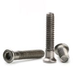
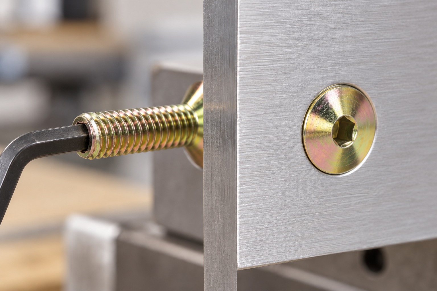
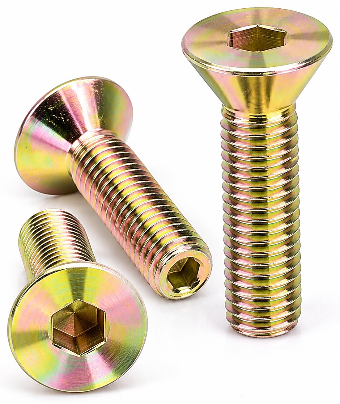
Countersunk screw seat depth depends on the countersink diameter, the through-hole diameter and the included angle. Choosing a flush head without checking that geometry can remove too much material from a thin panel. The design review should connect screw head dimensions to the actual seat, remaining thickness, contact pattern and permitted flushness.
For an ideal conical seat with included angle α, entrance diameter D and lower opening diameter d, h = (D − d) / [2 tan(α/2)]. This is the axial depth between those two diameters. The actual screw head may include edge radii or a small cylindrical rim, so use the specified head envelope when assessing final flushness.
| Fixed diameters | Included angle | Calculated depth h | Remaining thickness in a 2.00 mm panel |
|---|---|---|---|
| D = 8.00 mm; d = 4.50 mm | 90° | 1.750 mm | 0.250 mm |
| D = 8.00 mm; d = 4.50 mm | 100° | 1.468 mm | 0.532 mm |
This comparison holds diameters constant to show geometric sensitivity. It does not authorize substituting a 100° head into a 90° seat. The screw and seat must be designed to match. The calculated remaining thickness is a geometric result, not a pull-through or fatigue rating.
At 90°, the ideal relation simplifies to h = (D − d)/2. Suppose D = 8.00 ± 0.10 mm, d = 4.50 ± 0.05 mm, and panel thickness t = 2.00 ± 0.10 mm. The deepest seat occurs at the largest entrance and smallest lower opening: hmax = (8.10 − 4.45)/2 = 1.825 mm. Minimum remaining thickness is therefore 1.90 − 1.825 = 0.075 mm.
The nominal calculation gave 0.250 mm, more than three times that limit result. This stack excludes angle tolerance, burrs, local thickness variation and surface finish. Add those effects where they matter. If the geometry approaches a knife edge, changing only the tightening torque does not restore missing panel material.
| Drawing control | Purpose |
|---|---|
| Seat included angle | Match the screw bearing cone |
| Entrance diameter or controlled seat depth | Locate the head axially |
| Panel minimum thickness | Protect the residual material |
| Head height above or below surface | Define the functional flushness requirement |
| Edge condition and finish stage | Avoid burr-supported or coating-dependent seating |
A screw can appear flush while contacting only near the top edge or near the lower part of the cone. An angle mismatch, burr or head transition interference can create this condition. Contact should be assessed together with the intended load path; appearance alone is insufficient.
The seating geometry also locates the screw laterally. If several countersunk fasteners are used to force a thin cover onto misaligned holes, the conical seats can distort the panel. Define whether the fasteners locate the panel or merely clamp it, and provide alignment through the intended features. Do not rely on tightening to correct a hole pattern that is outside its positional limits.
For a machine cover that must pass close to another surface, flushness may be a clearance requirement. For a thin electronic enclosure, the same head can leave insufficient panel support. Possible design routes include a smaller matched head and seat, a thicker local feature, a suitable formed seat, or a different head style. Each route needs its own assembly and load check.
A low-profile head can avoid cutting a conical seat, but changes the outside height and bearing footprint. See our head-height and drive-depth design guide when comparing alternatives. A shallow head is not automatically stronger or easier to tighten; sufficient recess engagement must still remain.
Measure the seat and the head against their respective drawings, then check the assembled head position with representative mating parts. Specify the surface used as the flushness reference, the accepted above-surface or below-surface range, and the assembly condition. Record whether measurements are before or after coating.
For production approval, include head diameter, cone angle, drive engagement, panel thickness, seat depth or diameter, burr condition and thread engagement. For a through-bolted construction, check the nut-side clearance and load path. For a tapped assembly, verify usable thread depth independently of the seat calculation. The seat-depth formula does not establish engaged thread length.
Yes, when the material thickness and required seat geometry permit it. Control the angle, diameter, depth and edge condition, then verify the assembled head position.
Reconsider them when the panel cannot support the required seat, when conical seating overconstrains alignment, or when repeated service damages the seat. Compare other head and joint designs.
It is often described as a flat-head screw, but terminology varies. Specify the head standard or drawing, included angle and drive type to avoid ambiguity.
Do not treat the two as matched. The different angles change the contact pattern, even if the head can be made to look flush.
Not necessarily. It changes head position and removes more supporting material. Check the required bearing geometry and remaining panel section before changing the depth.
Send the screw head dimensions, panel material and thickness range, seat angle, flushness limit and mating-thread details. SHISHITONG can review a custom head geometry against the available assembly space.
sst@szsst88.com Attach your drawing in your email app.
2026.10.28
kalyn

 +86 13143444311
 sst@szsst88.com