Tel:
+86 13143444311
Email:sst@szsst88.com
Fax:+0086-755-27322278
Address:Building 9, First Industrial Zone, Tantou Industrial City, Songgang Street, Baoan District, Shenzhen 518105, Guangdong, China
Long screws can bind in a multi-layer assembly even when each individual part appears acceptable. The cause may be offset clearance holes, a bowed shank, an unsuitable grip length, insufficient blind-hole clearance or a damaged thread. The fastest way to investigate is to identify where resistance begins before changing the screw specification or increasing installation torque.
Resistance before the screw reaches the mating thread suggests a passage or alignment problem. Resistance during thread engagement requires a separate check of pitch, thread condition, usable depth and friction. Neither symptom is a reason to force the assembly together.
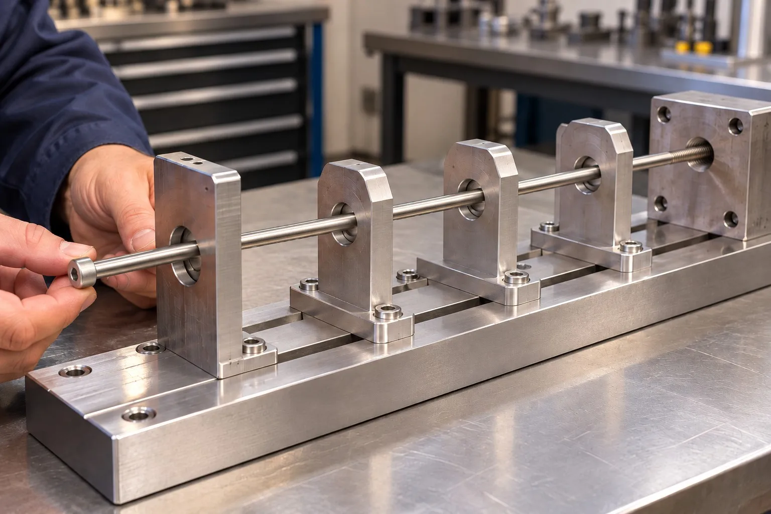
Record how far the screw enters, whether it has started engaging the mating thread, and whether the head has reached its bearing surface. Keep the affected screw and mating parts together for inspection. Repeated powered attempts can erase the original damage pattern.
| Observed symptom | Check first | What not to assume |
|---|---|---|
| Stops before reaching the threaded part | Hole alignment, burrs, finish buildup and shank geometry | That the thread pitch is the cause |
| Starts crooked or becomes tight immediately | Tool alignment, thread start, diameter and pitch | That more torque will correct the alignment |
| Stops with a gap under the head | Blind-hole bottoming, incomplete threads and shank interference | That the joint is already clamped |
| Becomes progressively rough after initially turning freely | Debris, damaged threads, galling and surface condition | That every tight thread is caused by a bent screw |
Clearance holes can each meet their diameter requirement while their assembled positions leave no straight passage. Review the common datum scheme, relative hole positions, angular error, locating features and the condition of the stack during inspection. A small angular mismatch becomes more significant over a longer distance.
Separate the locating function from the clamping function. Where precise location is required, use the designed locating features or fixture rather than pulling an offset stack into position with the long screw. Increasing every clearance hole is not automatically acceptable: edge distance, bearing support and movement under load still matter.
Check parts in their intended assembly sequence. Introduce the fasteners with the layers supported and located, confirm the specified thread start, and then follow the approved seating and tightening sequence. Do not fully tighten one corner prematurely if it distorts the stack and blocks the remaining holes.
For a screw axis fixed by the entry guide or receiving thread, the lateral displacement caused by an angular error is e = L tan θ, where L is the distance from the alignment reference. The same angle creates more offset as the insertion distance increases.
| Distance L | Offset at θ = 0.10° |
|---|---|
| 100 mm | 0.175 mm |
| 300 mm | 0.524 mm |
| 500 mm | 0.873 mm |
These values are calculated geometric offsets, not measured production errors or recommended tolerances. With a 6.00 mm maximum passing diameter and a 6.60 mm minimum clearance hole, the available radial clearance is (6.60 − 6.00)/2 = 0.30 mm. An axis constrained at 0.10° would therefore exceed that clearance at a 300 mm distance, even before burrs, bow or coating buildup are included.
Apply the calculation to the actual constraint: a floating screw can translate or tilt before engagement; a screw already located by a guide or thread has less freedom. Review the complete path in the assembled condition. Use the largest diameter that passes through each hole, including the thread crest where applicable. Treat radial offset and diametral position tolerance separately; they are not interchangeable numbers.
Specify the length reference explicitly. Most non-countersunk screw lengths are measured from the underside of the head; countersunk forms commonly use an overall-length reference. The drawing must remove any ambiguity.
Evaluate the tolerance extremes. The thickest stack with the shortest permitted screw can reduce engagement; the thinnest stack with the longest screw can cause bottoming. For a partially threaded design, also check whether the unthreaded section or thread runout prevents the head from seating.
As an engineering reference, NASA-STD-5020B threaded-fastener guidance distinguishes grip and thread engagement and addresses avoiding bottom contact and incomplete internal threads in blind holes. This reference addresses spaceflight hardware; it is cited here for the engineering principle, not as a certification or compliance claim. Industrial joint engagement must be specified from its load, materials and geometry.
For an under-head length L and assembled grip G, the tip penetration into the receiving part is P = L − G after the head seats. Let H be the axial distance from the receiving face to the nearest bottom obstruction on the screw axis. Then physical tip clearance is C = H − P. Drill-point depth and full-thread depth are separate dimensions.
| Dimension inputs for this calculation | Permitted range |
|---|---|
| Under-head screw length L = 200.0 ± 0.3 mm | 199.7–200.3 mm |
| Assembled grip G = 185.0 ± 0.5 mm | 184.5–185.5 mm |
| Depth to bottom obstruction H = 17.0 ± 0.2 mm | 16.8–17.2 mm |
| Worst-case result | Calculation |
|---|---|
| Minimum penetration: 14.2 mm | 199.7 − 185.5 |
| Maximum penetration: 15.8 mm | 200.3 − 184.5 |
| Minimum physical bottom clearance: 1.0 mm | 16.8 − 15.8 |
Engineering interpretation: nominal dimensions suggest 2.0 mm bottom clearance, but the tolerance extremes reduce it to 1.0 mm. Compare that 1.0 mm with the clearance required by the joint drawing. These stated inputs explain the calculation; they are not a standard length recommendation or a Shi Shi Tong product acceptance limit.
Penetration is not full-thread engagement. Determine the axial overlap of complete external and internal threads, excluding the tip lead, entry chamfer, thread runout and incomplete tapped threads. A positive bottom clearance can coexist with insufficient engagement. For partially threaded screws, also verify that the smooth shank does not reach the internal thread before the head seats.
To choose an acceptable length range, work backward from both requirements: the shortest screw in the thickest stack must provide the specified complete-thread overlap; the longest screw in the thinnest stack must retain the specified bottom clearance. If the ranges do not overlap, change the joint geometry, usable thread depth or tolerance allocation instead of selecting a compromise nominal length.
Inspect the shank using the drawing’s agreed method. A visual roll on a bench can reveal an obvious problem, but it is not a substitute for a defined acceptance test. A rotating indicator reading can combine form, alignment and setup effects; it should not automatically be reported as straightness.
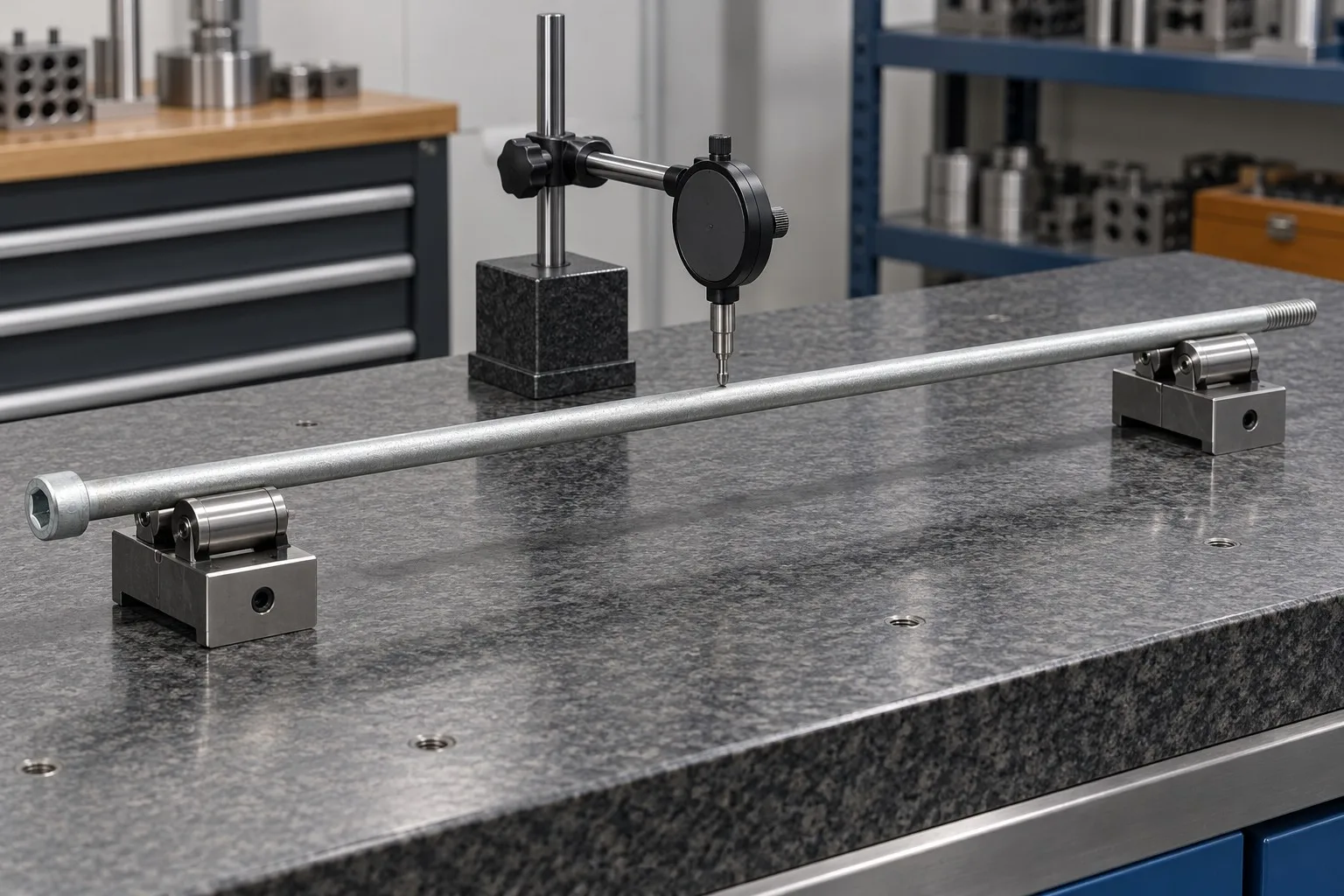
For long, slender parts, support spacing and orientation affect deflection under the part’s own weight. Record these conditions so supplier and receiving inspection are comparable. Check relevant dimensions in the finished condition after the specified treatment or coating.
Packaging and assembly handling also matter. Support long parts during transport and presentation to the workstation, protect the threads, and avoid bending them to make them enter an offset hole. If binding changes after unpacking or handling, investigate that stage rather than changing manufacturing tolerances without evidence.
When stainless mating threads become rough or seize, consider galling separately from geometric interference. Bossard’s galling guidance describes adhesion between mating thread surfaces and mitigation through design and surface control. Any lubricant or coating change also changes friction and therefore requires review of the tightening process.
| Inspection item | Record with the result |
|---|---|
| Shank geometry | Support positions, part orientation, measured length, measurement locations and the specified geometric characteristic |
| Thread fit | Thread designation and class, gauge identification, finished coating condition and any location where resistance begins |
| Assembly passage | Fixture datums, stack configuration, passing diameter and insertion depth at first contact |
| Blind-hole fit | Actual grip, screw length, complete-thread limits and depth to bottom obstruction |
Elastic sag under the screw’s own weight can change an indicator reading when support spacing changes. Keep the support arrangement consistent and distinguish reversible deflection from permanent bow. A larger runout reading after moving the supports does not, by itself, prove that the screw became less straight.
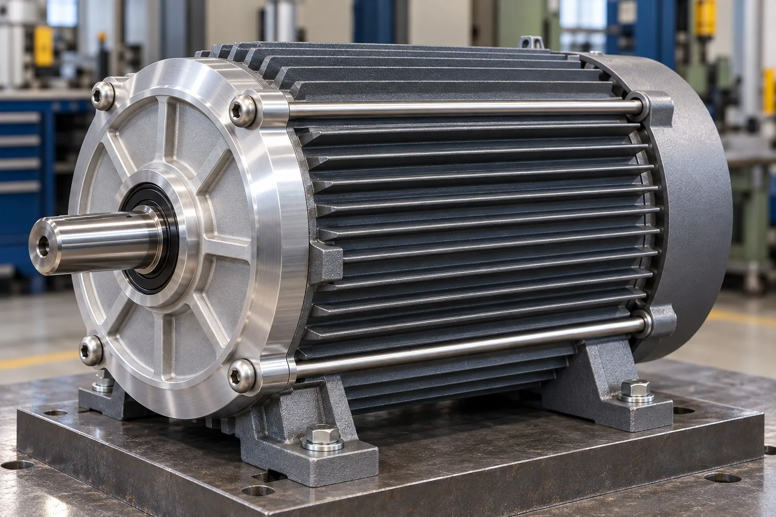
A long fastener may connect separated end plates across a housing. Review the locating interfaces and the hole path before clamping. Binding can come from a shifted end plate even if the screw is straight. Confirm service access for both installation and removal.
Layer thickness, spacer length and washer variation affect the assembled grip. A change to one layer may alter both engagement and bottom clearance. Inspect the complete stack against the intended datums, and keep the fastener length revision linked to the assembly drawing.
Restricted access can make the driver approach at an angle. Provide the correct tool path and support the fastener during insertion. If a connection needs deliberate alignment adjustment, design that adjustment into the assembly instead of relying on fastener bending.
Start with our long and extra-long screw configurations, then provide the dimensions and operating conditions that determine the custom design:
If parts already bind, add photographs of the contact marks, the insertion distance where resistance starts and the affected mating components. Shi Shi Tong can review the drawing, geometry and production route before sample approval. Manufacturing feasibility and acceptance criteria should be confirmed for the specific combination of length, diameter and material.
In a metal multi-layer assembly, first determine whether the screw stops in a clearance hole or after entering the mating thread. Possible causes include offset holes, burrs, a bowed shank, incorrect thread geometry, incomplete threads or bottoming in a blind hole. A gap under the head means seating has not been established; do not treat the torque reading alone as proof of clamping.
The tip may not yet have reached the receiving thread, the mating nut or insert may be rotating, or a thread may be damaged. Confirm engagement and inspect the receiving component. Increasing speed does not restore a stripped thread or secure a loose insert.
For long machine screws, align and support the assembly, remove burrs and contamination, verify thread compatibility and use the correct tool. Apply only the specified lubrication or finish. If resistance remains, find the interference rather than forcing the screw or making an unapproved change to the holes.
No. Additional length only helps if it serves the joint design. Excess length can bottom in a blind hole, interfere with nearby parts or place the thread runout incorrectly. Strength and reliability depend on the load path, material, engagement, preload and mating components.
Choose according to where the thread is needed and what the shank must do. A partial thread can place a smooth section through the stack, but its length and runout must allow proper seating and engagement. A fully threaded version does not correct an offset hole path. Review the complete assembly rather than selecting by appearance.
Send Shi Shi Tong your screw drawing and assembly section for a review of the dimensions, material and manufacturing route.
Include: length and diameter, thread specification, material, finish and quantity. For a binding problem, add the insertion depth where resistance starts and whether the head seats.
Email: sst@szsst88.com · Attach your drawing in your email app.
2026.10.22
kalyn

 +86 13143444311
 sst@szsst88.com