
 +86 13143444311
 sst@szsst88.com

ENGINEERING GUIDE / DESIGN & INSPECTION
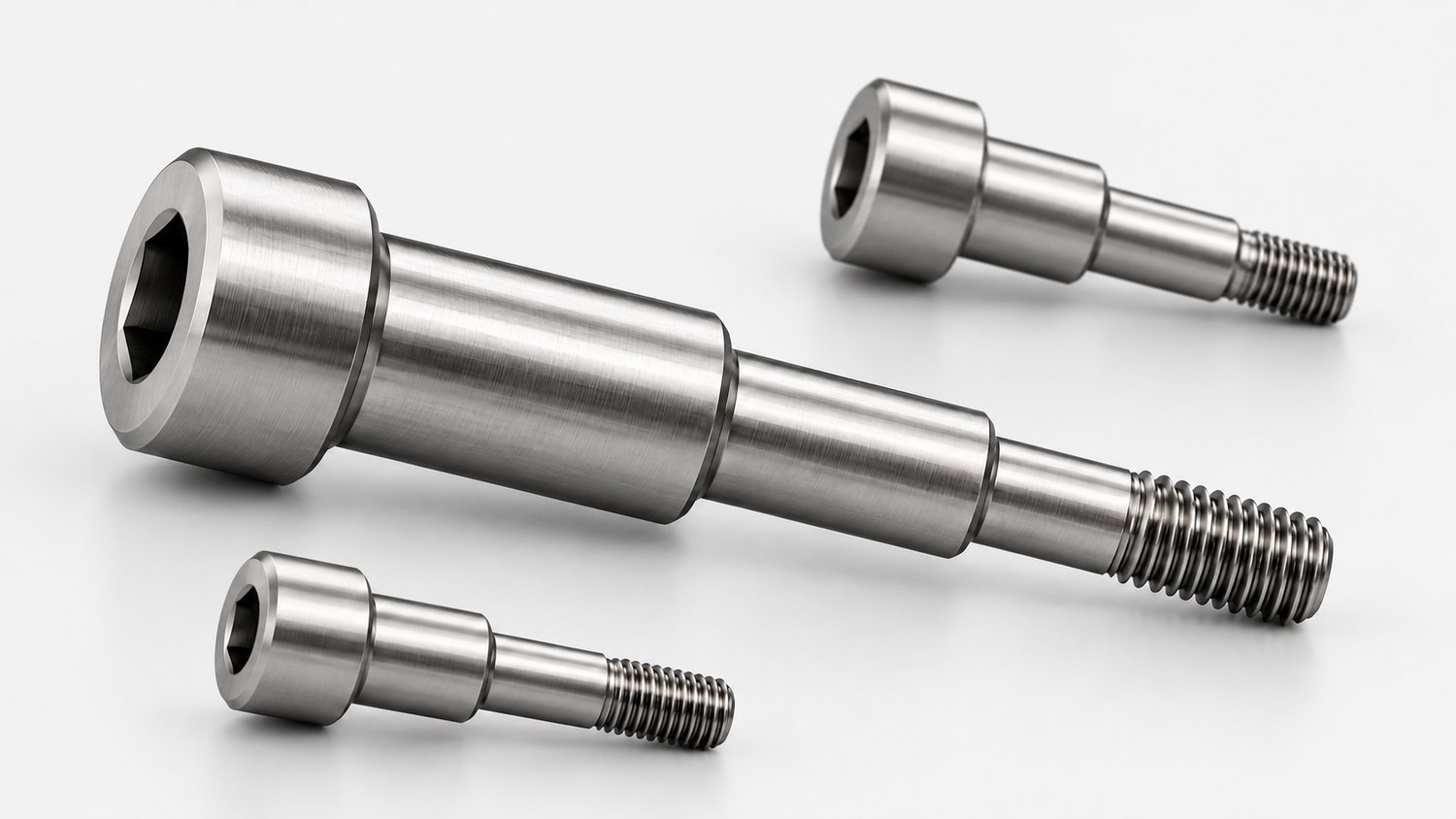
For multi-step shoulder screws, specify each shoulder by its function, mating dimensions and inspection requirements. Then check the complete assembly at its tolerance limits before selecting the manufacturing route. A thread size alone does not define a stepped fastener.
A multi-step shoulder screw can combine positioning, spacing and fastening in one component. Those functions must be defined separately: a diameter that guides a moving part may need a different fit from a surface that locates a fixed component. This guide is for engineers preparing a custom drawing and buyers coordinating its manufacture.
In this guide
Industry assembly applications
01 Functions / 02 Fits / 03 Clearance
04 Transitions & seating / 05 Manufacturing routes
06 Inspection / 07 Drawing checklist / FAQ
Industry assembly applications
Automation equipment: pivot arms and linkages
A pivot joint needs secure fastening while allowing the moving arm to rotate. If tightening traps the moving stack, the arm can bind; excessive axial clearance can allow unwanted movement. Review the shoulder span, bushing fit and seating surfaces together.
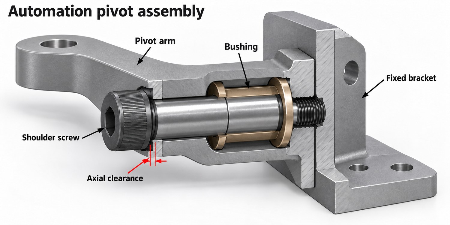
Drawing-review focus: identify the fixed and moving parts, the intended stop face, the mating bushing limits and the acceptable end play. Provide the operating load and motion requirements so the complete joint can be assessed.
Packaging and conveying equipment: guide rollers
A guide roller must turn without its end faces being unintentionally pinched against the head or mounting bracket. Too much axial movement can also affect guidance. Review the roller width, sleeve bushing, smooth support length and threaded mounting as one assembly.
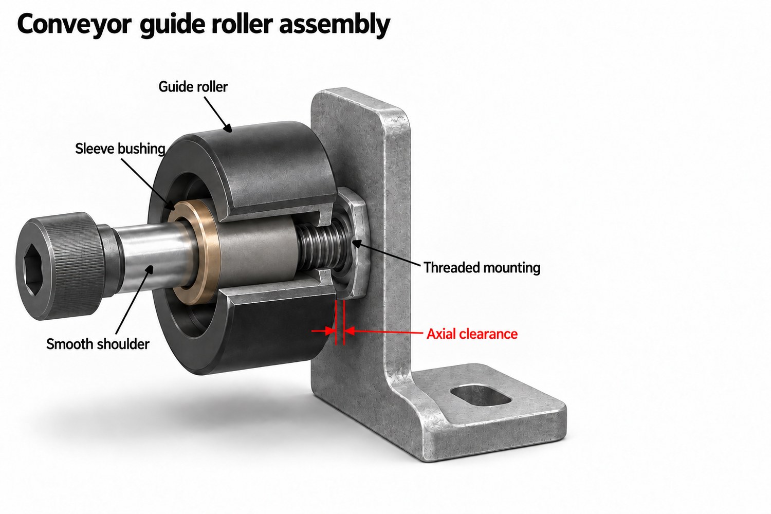
Drawing-review focus: check the complete tolerance stack and confirm free rotation after tightening. Specify loads, speed, lubrication and environmental conditions where relevant; the illustrations do not define production dimensions or a validated load rating.
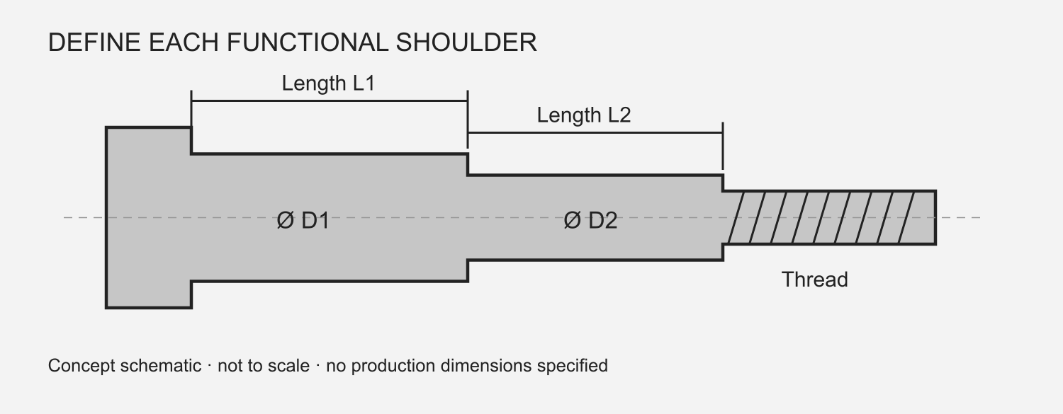
1. Start with what each step must do
Mark which surfaces locate, rotate, slide, stop or clamp. Identify the intended load path and the surface that stops axial travel when the fastener is tightened. Without that information, a supplier may produce every listed dimension correctly while an important assembly relationship remains undefined.
For background on the basic geometry, see our guide to shoulder screw types and applications. Here the focus is the relationship between multiple shoulders and their mating components.
Locating diameter
Mating hole limits, functional axis and required fit
Nominal diameter alone does not establish alignment or clearance.
Moving interface
Bushing or bearing interface, motion and operating conditions
A freely moving part must remain free after tightening.
Axial stop
Seating face and distance to the opposing restraint
This relationship controls spacing or end play.
Threaded end
Thread designation, useful engagement and available hole depth
Bottoming and incomplete threads can affect seating.
2. Specify the fit with the mating part
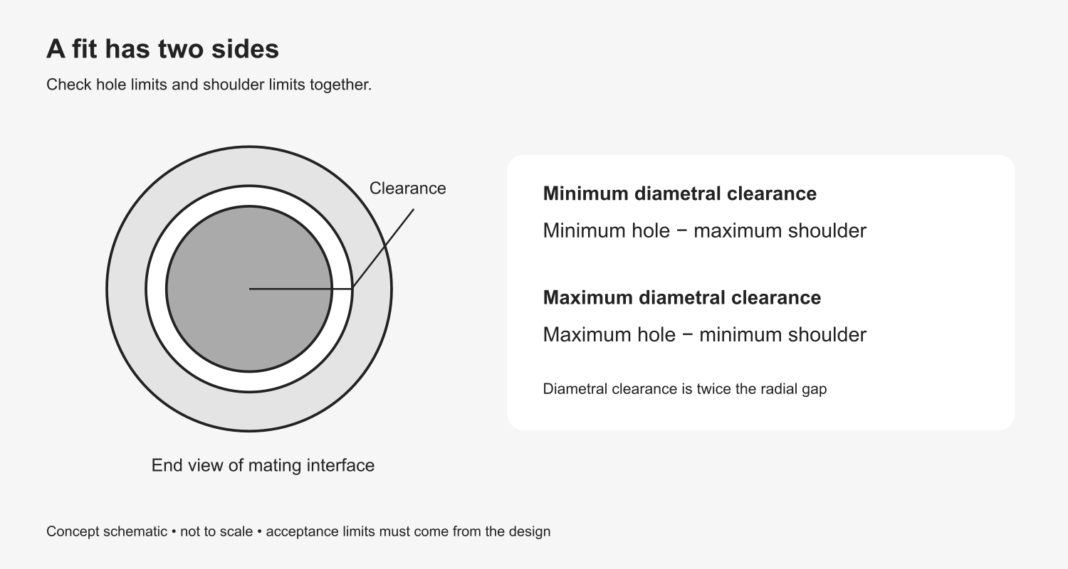
Provide both sides of a critical fit. A shoulder tolerance is incomplete as a design decision without the hole or bushing limits, the required motion and the operating conditions. Do not copy a fit designation from an unrelated catalogue part and assume it will work.
For a simple cylindrical clearance interface, minimum diametral clearance is the minimum hole diameter minus the maximum shoulder diameter. Maximum clearance uses the opposite limits. Roundness, surface texture, alignment and temperature can still influence function, so this dimensional calculation is only part of the review.
Apply tighter requirements where they protect an identified function. Avoid giving every diameter the same narrow tolerance merely because the assembly is described as “precision.”
3. Check axial clearance at both tolerance limits
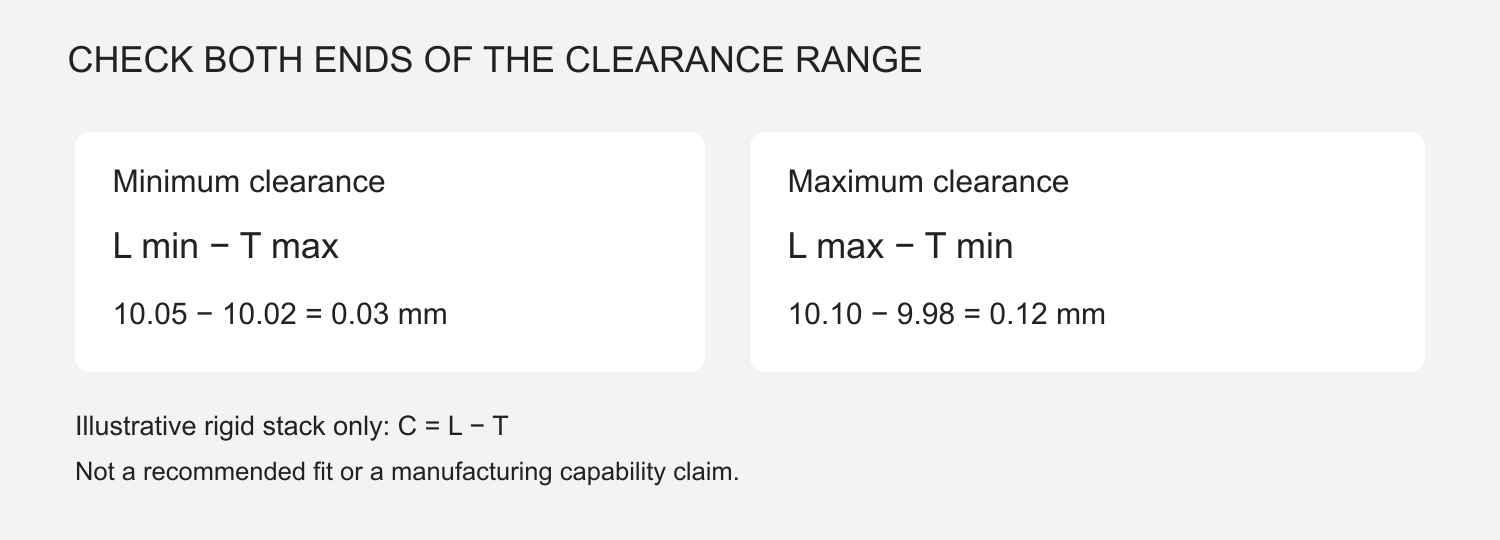
A nominal gap can disappear when the shortest available shoulder span meets the thickest retained component stack. Excessive clearance can create a different problem: unwanted axial movement. Check both conditions.
Worked example — illustrative limits only
Assume a rigid assembly where L is the distance between the two axial restraint surfaces and T is the retained stack thickness. For this arrangement only, clearance C = L − T.
If L = 10.05–10.10 mm and T = 9.98–10.02 mm, the clearance range is 0.03–0.12 mm. The designer must decide whether that entire range is acceptable.
Include every component that lies in the actual stack. If washers, coatings, compliant materials or preload-induced deformation affect the axial relationship, the simplified model above needs to be extended. SPIROL’s explanation of tolerance accumulation provides related background; its compression-limiter application is distinct from this illustrative screw assembly.
4. Review transitions, seating and thread runout
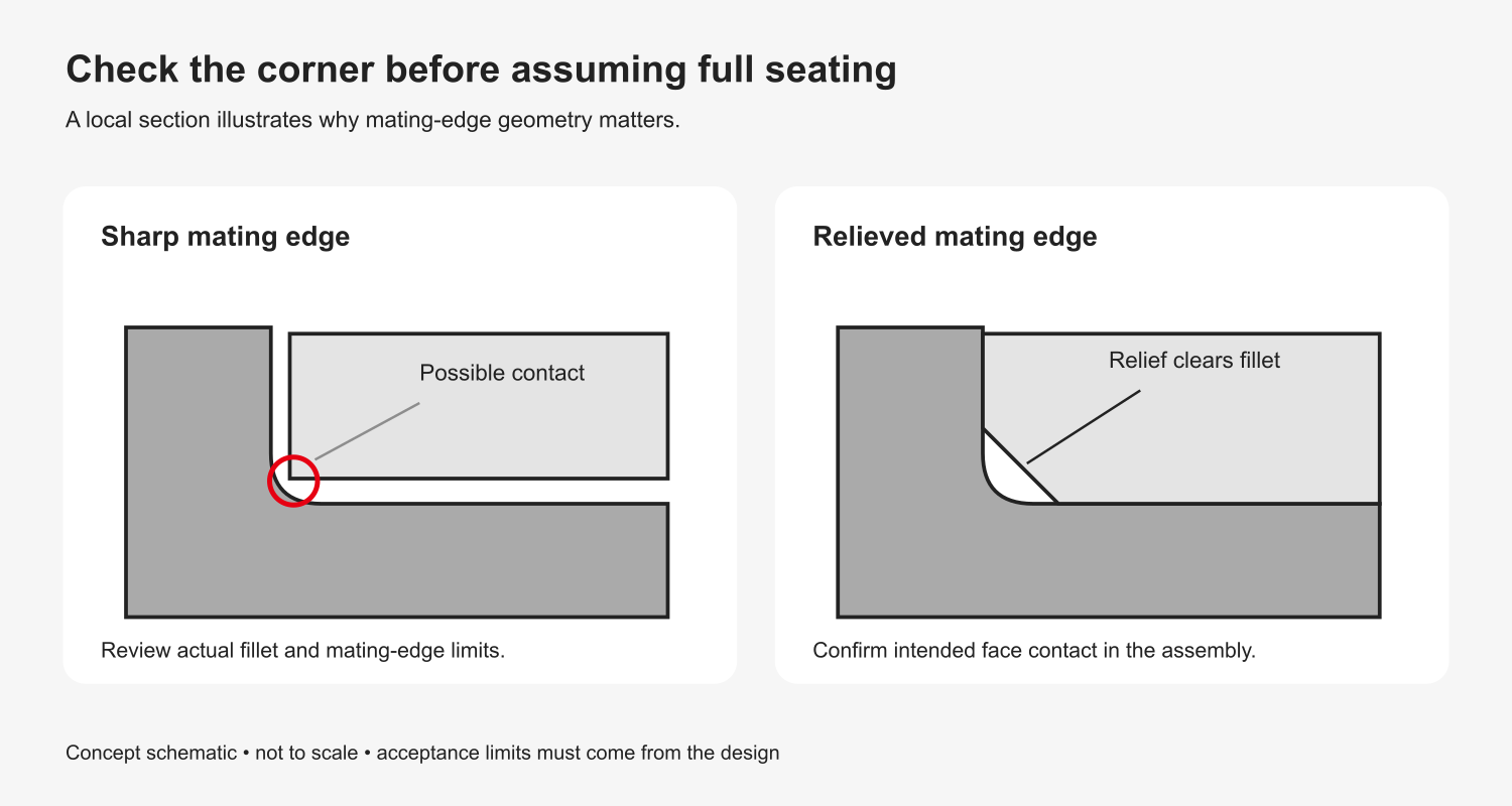
Inspect the transitions between adjacent diameters and beneath the head. A mating hole edge can contact a fillet before the intended bearing face seats. Show the relevant chamfer or relief on the assembly detail rather than assuming a sharp corner.
At the threaded end, distinguish the complete usable thread from the transition region. Check engagement, blind-hole depth and clearance at the shoulder stop together. A screw that reaches the bottom of a hole before seating cannot be assessed by tightening torque alone.
5. Select a manufacturing route around the critical features
Complex geometry does not automatically require a fully machined part, and a high quantity does not automatically make cold heading suitable. Material condition, forming geometry, tooling, secondary operations and inspection requirements all matter.
Cold heading with subsequent thread rolling
Can the specified material and geometry be formed and controlled within the agreed requirements?
Forming plus secondary machining
Can forming create the blank while machining finishes selected functional surfaces?
Turning or precision machining
Does the geometry, material, trial quantity or required feature access favor a machined route?
Shi Shi Tong reviews complex custom screw drawings against the proposed material, geometry, process and inspection plan. Explore the special screw product range for related configurations. Feasibility and tolerances are confirmed for the individual project.
6. Agree how the critical features will be measured
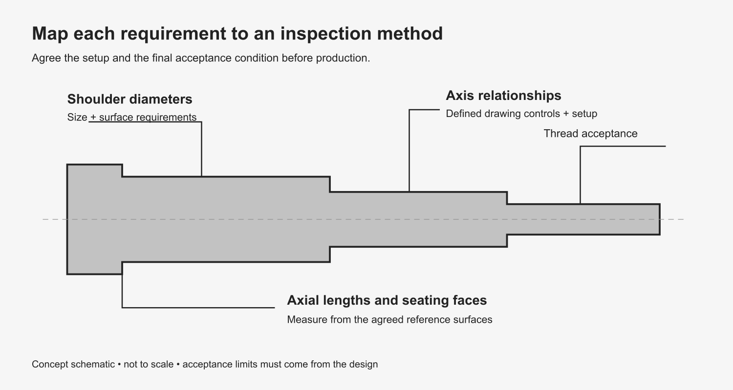
State which surfaces establish the measurement setup and which geometric relationships matter to the assembly. Choose the appropriate drawing controls with the design engineer; terms such as runout, position and coaxial alignment are not interchangeable acceptance requirements.
Match the inspection method to the feature. Accessible diameters and lengths, stepped profiles, threads and axis relationships may require different methods. Agree whether acceptance applies before or after surface treatment, and identify any functional check using representative mating parts.
7. Prepare a complete drawing-review package
- Revision-controlled drawing, units and applicable drawing standard.
- Material grade and condition, finish and final acceptance state.
- Shoulder diameters, lengths, mating-part limits and required motion.
- Thread details, transition geometry and seating requirements.
- Critical geometric controls, inspection methods and sample approval criteria.
- Prototype quantity, expected production volume and application conditions.
Technical FAQ
Does a multi-step screw need the same tolerance on every shoulder?
No. Define each tolerance from its function and mating interface. A non-locating section may not need the same control as a bearing or guiding surface.
Should a shoulder always be longer than the retained component?
No universal rule applies. A moving component may require positive clearance, while a clamped stack has a different requirement. Define the intended restraint surfaces and load path first.
Does an approved machined prototype validate a formed production part?
It validates only what was actually tested. If the production route changes, agree which material, dimensional, surface and functional requirements must be verified again.
Have a stepped screw drawing to review?
Send the part drawing with the mating component dimensions, material, finish, quantities and required movement. Shi Shi Tong can review the proposed manufacturing route and inspection requirements before tooling or sample production.